A2 and D4 (not connected):
A2: 1 / D4: 1
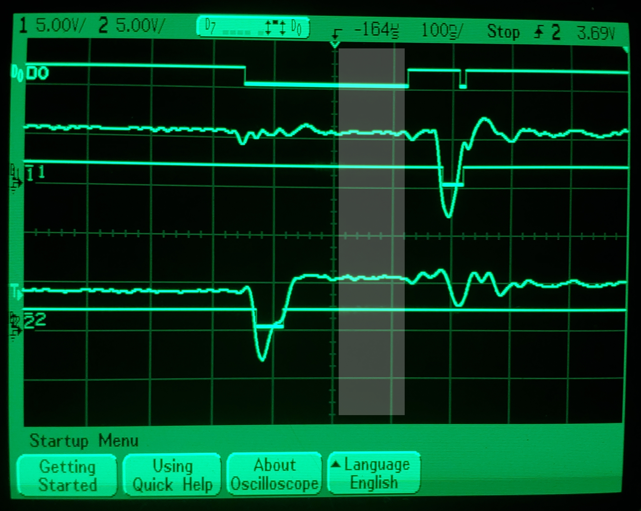
A2: 0 / D4: 0
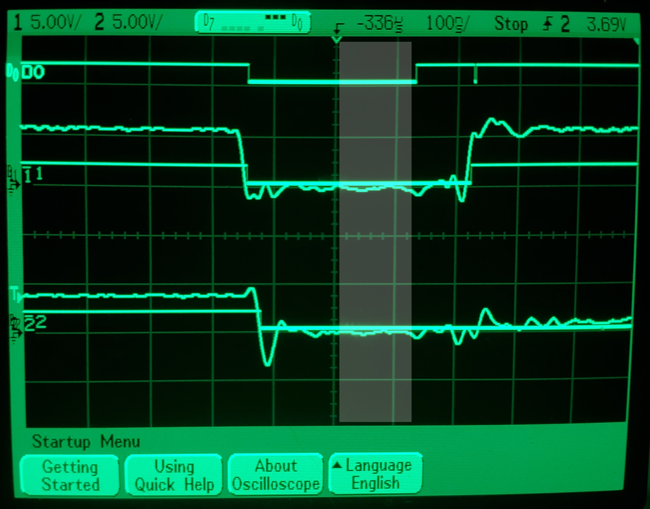
A2: 1 / D4: 0
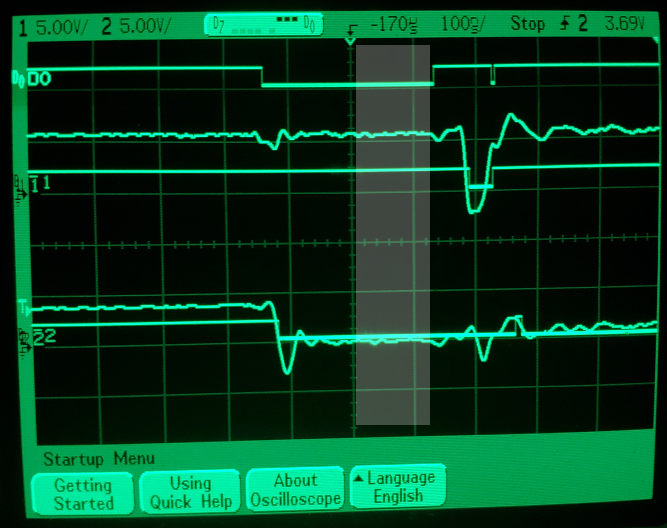
A2: 0 / D4: 1
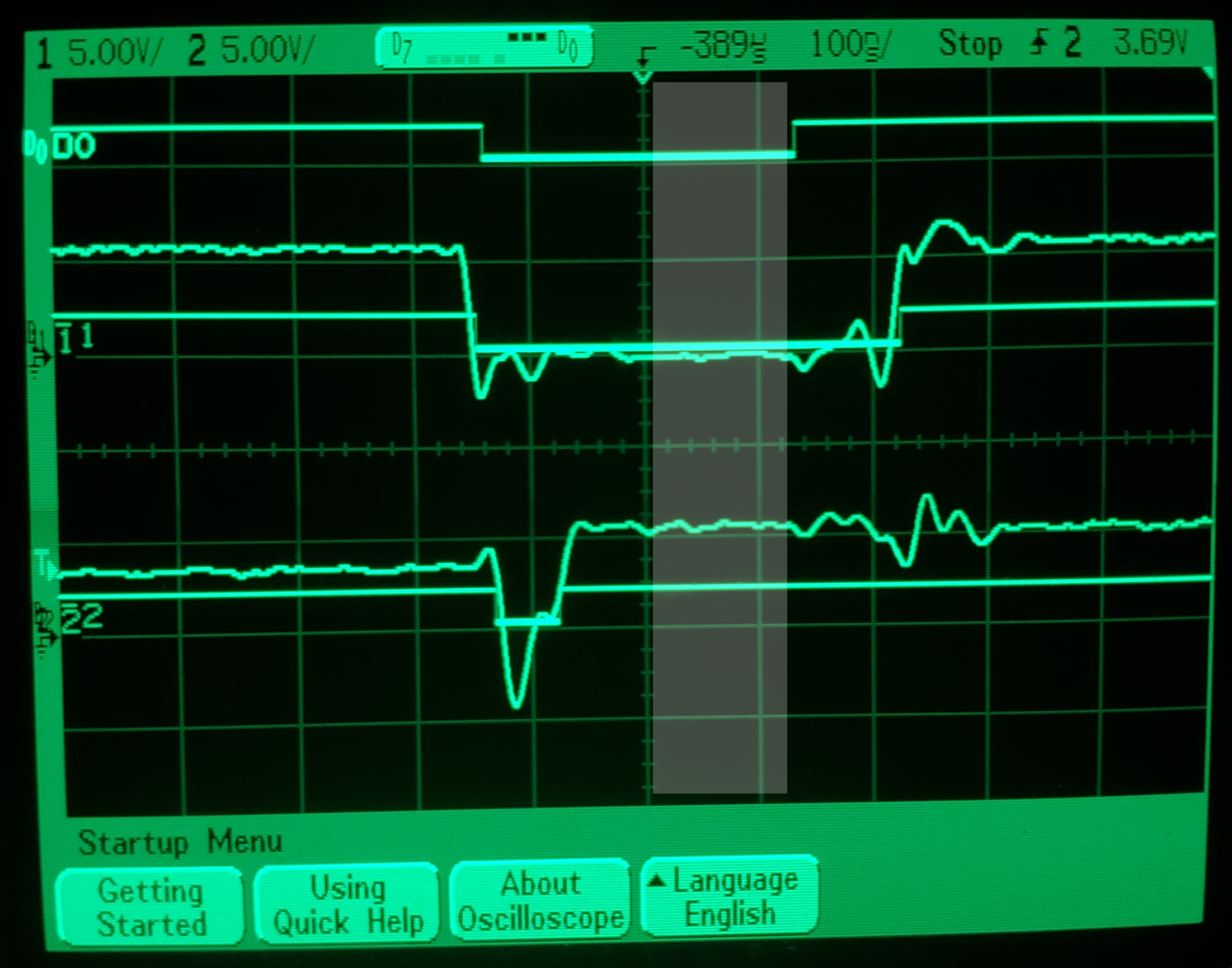
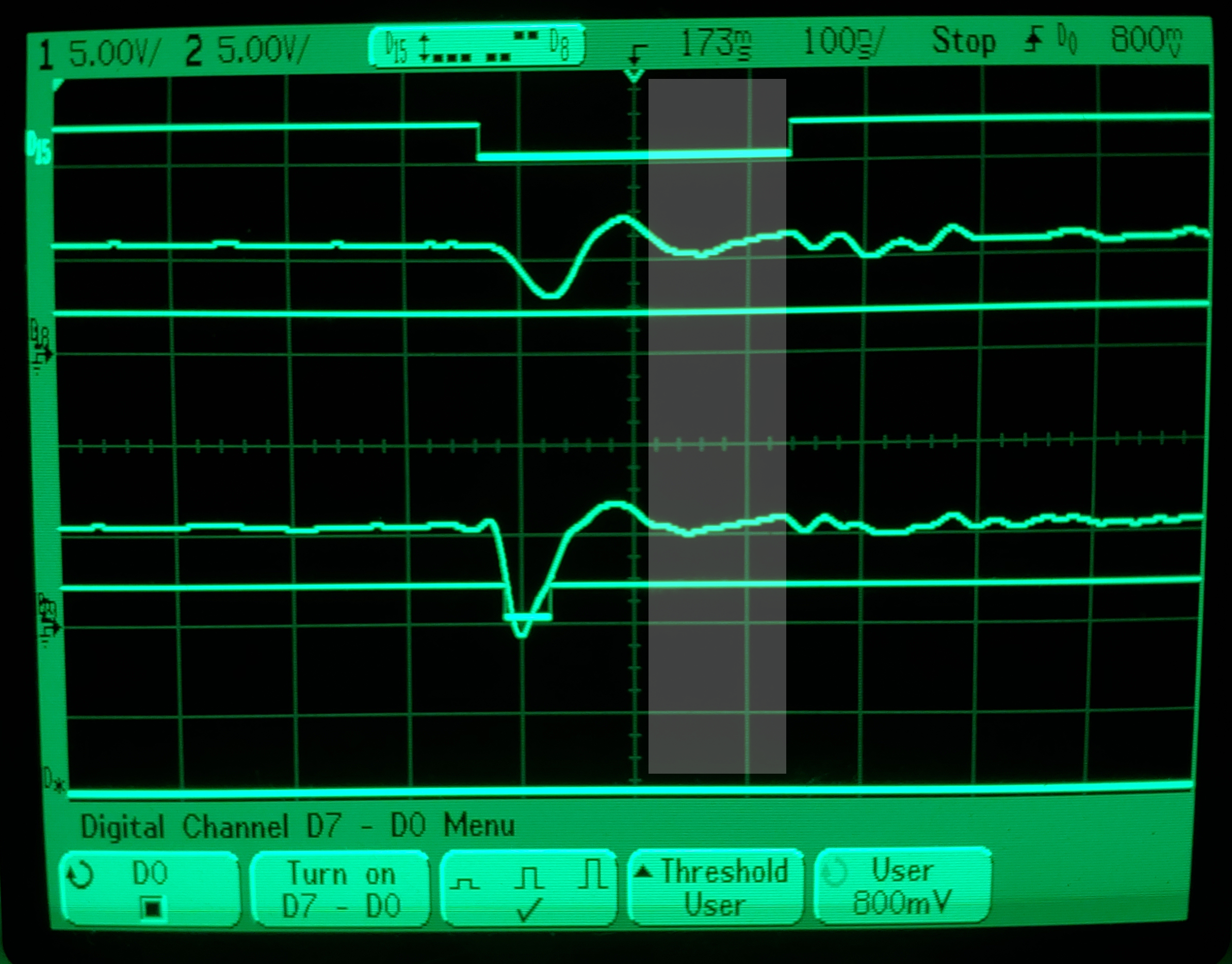
ROM data gets 'warbled' when the normally parallel ROM-CPU lines are cross-connected, causing strange synthesis effects. These oscilloscope images taken from probing the Casio MT-240 ROM Address line A2 connected to Data line D4.
A2 and D4 (not connected):
A2: 1 / D4: 1

A2: 0 / D4: 0

A2: 1 / D4: 0

A2: 0 / D4: 1

As expected, the logic levels are clearly defined in each case.
Taking a closer look, both A2 and D4 are normally held High when hi-Z, and when data is valid, the High voltage is around 5.5V for both lines. Note that A2: "1" takes a dip after the valid data, and that D4 takes a dip, regardless of level, before the valid data. These signature dips reveal something interesting in the next image set.
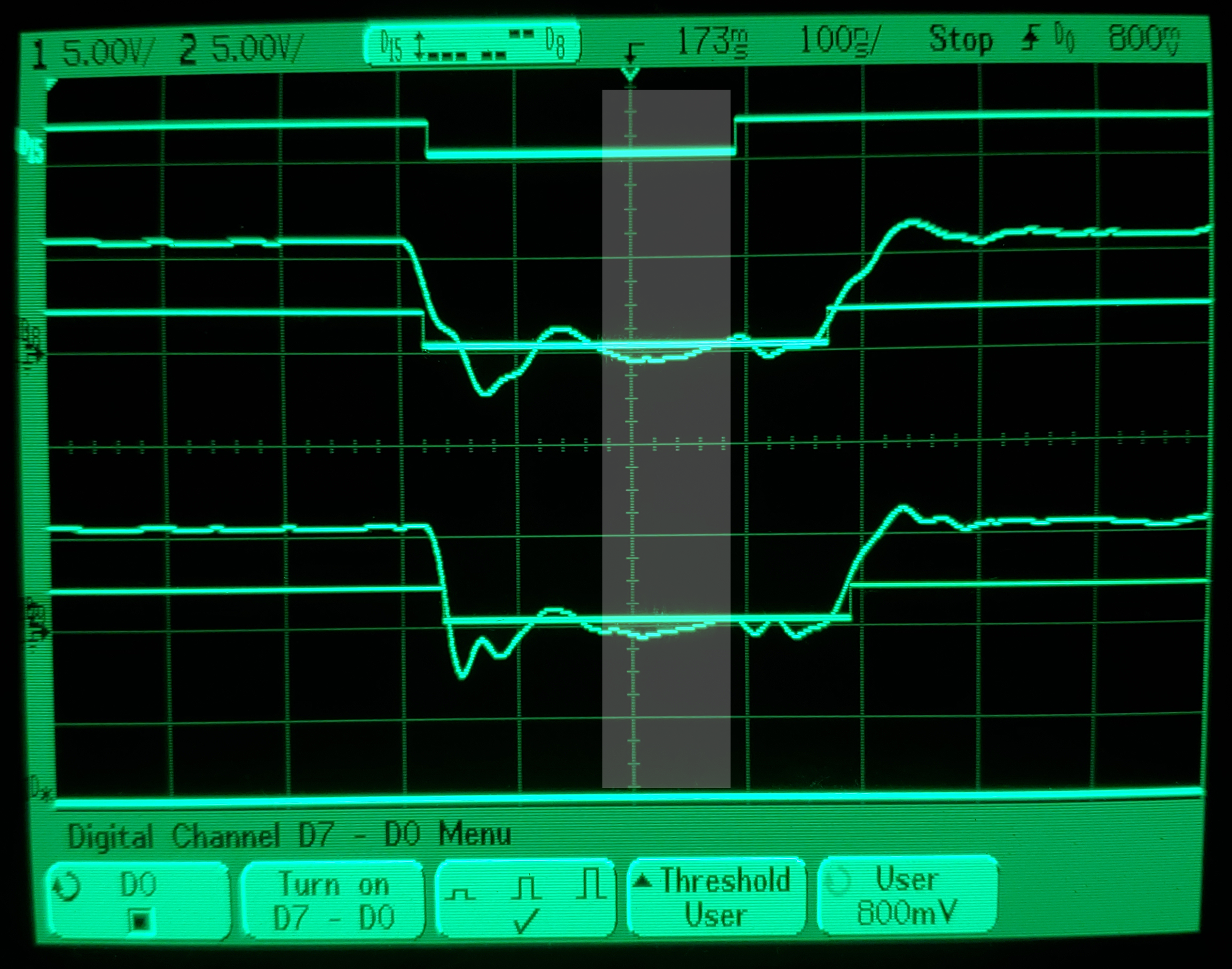
A2 and D4 (~120ohms):
A2: 1 / D4: 1
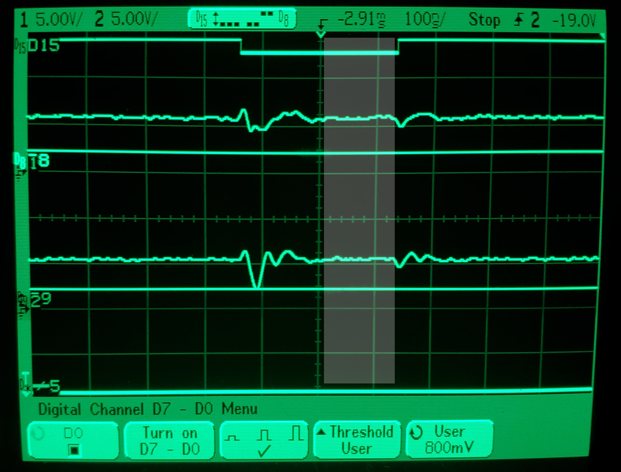
A2: 0 / D4: 0
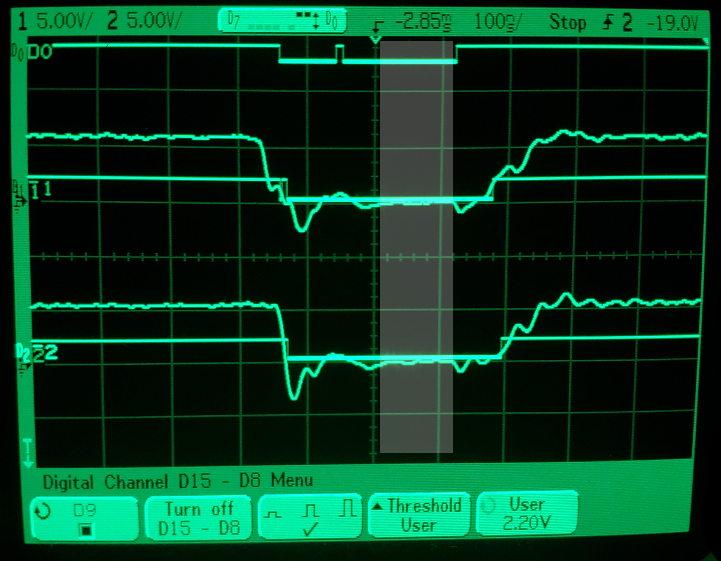
A2: 1 / D4: 0
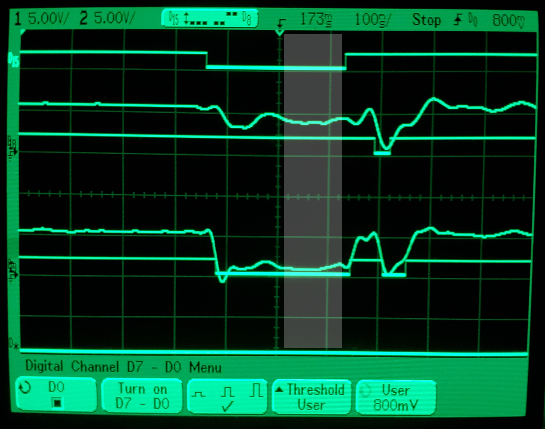
A2: 0 / D4: 1
Let's look closer at each case, comparing it to the not-connected traces above:
Case A (1/1): The big difference is that both A2 and D4 have lost that huge dip before and after. Both have been smoothed out.
Case B (0/0): A2 now shares the dip before from D4.
Case C (1/0): D4's low level is now higher, pulled up from A2.
Case D (0/1): D4's high level is now lower, pulled down from A2.
<The high levels in 0/1 1/0 cases are significantly lower. However, because they still fall within the high range, all four cases still pass the same data. This means that there is no change to the CPU and thus no change in the program or sound.
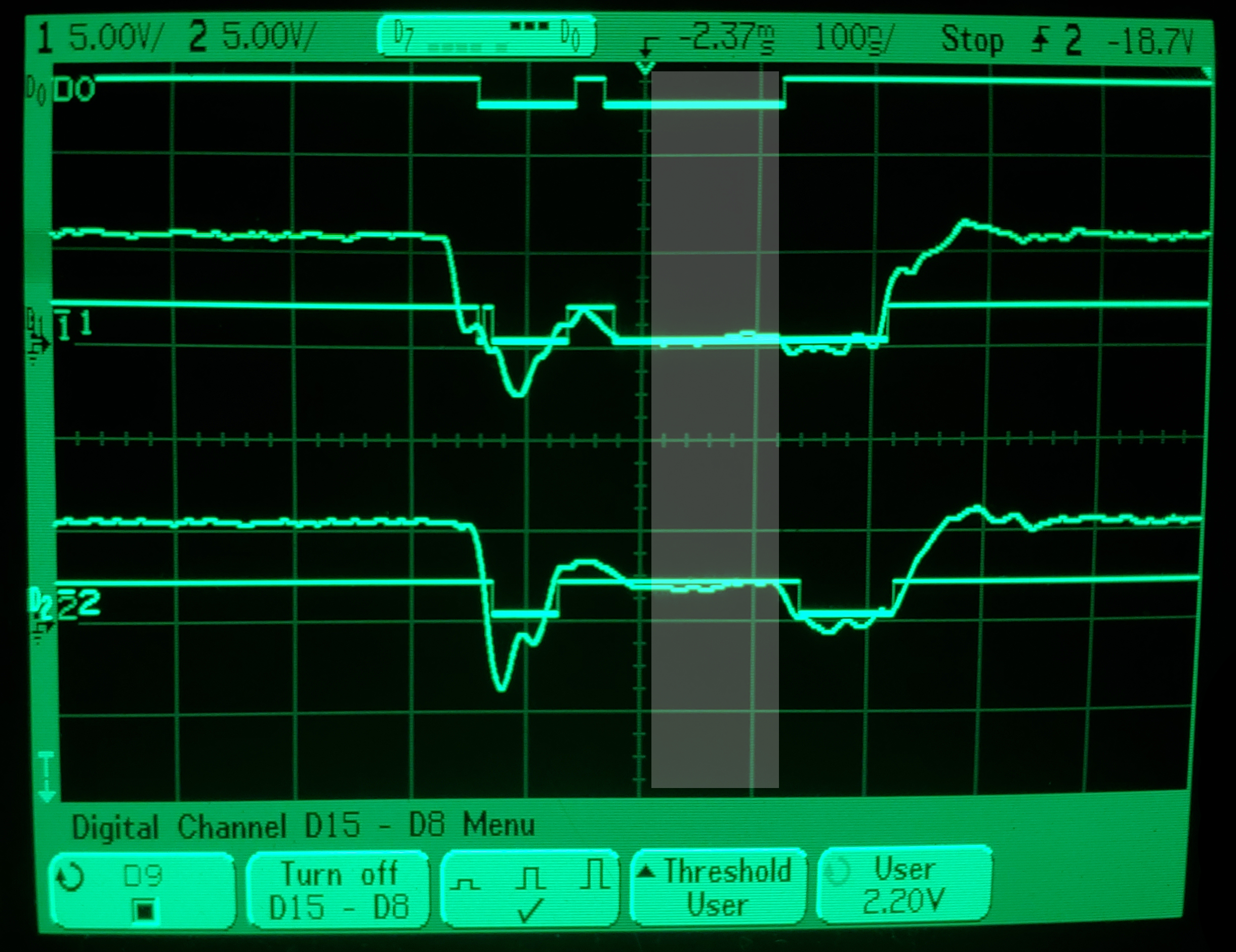
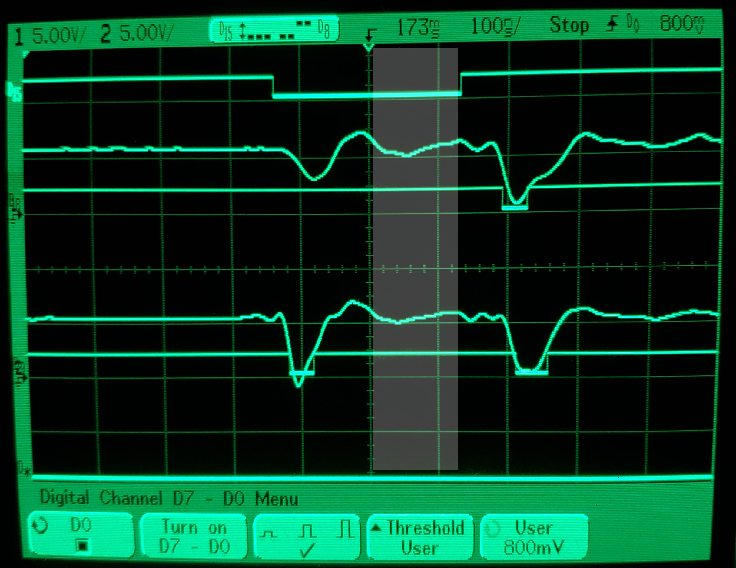
A2 and D4 (~95ohms):
A2: 1 / D4: 1
A2: 0 / D4: 0
A2: 1 / D4: 1
A2: 0 / D4: 0
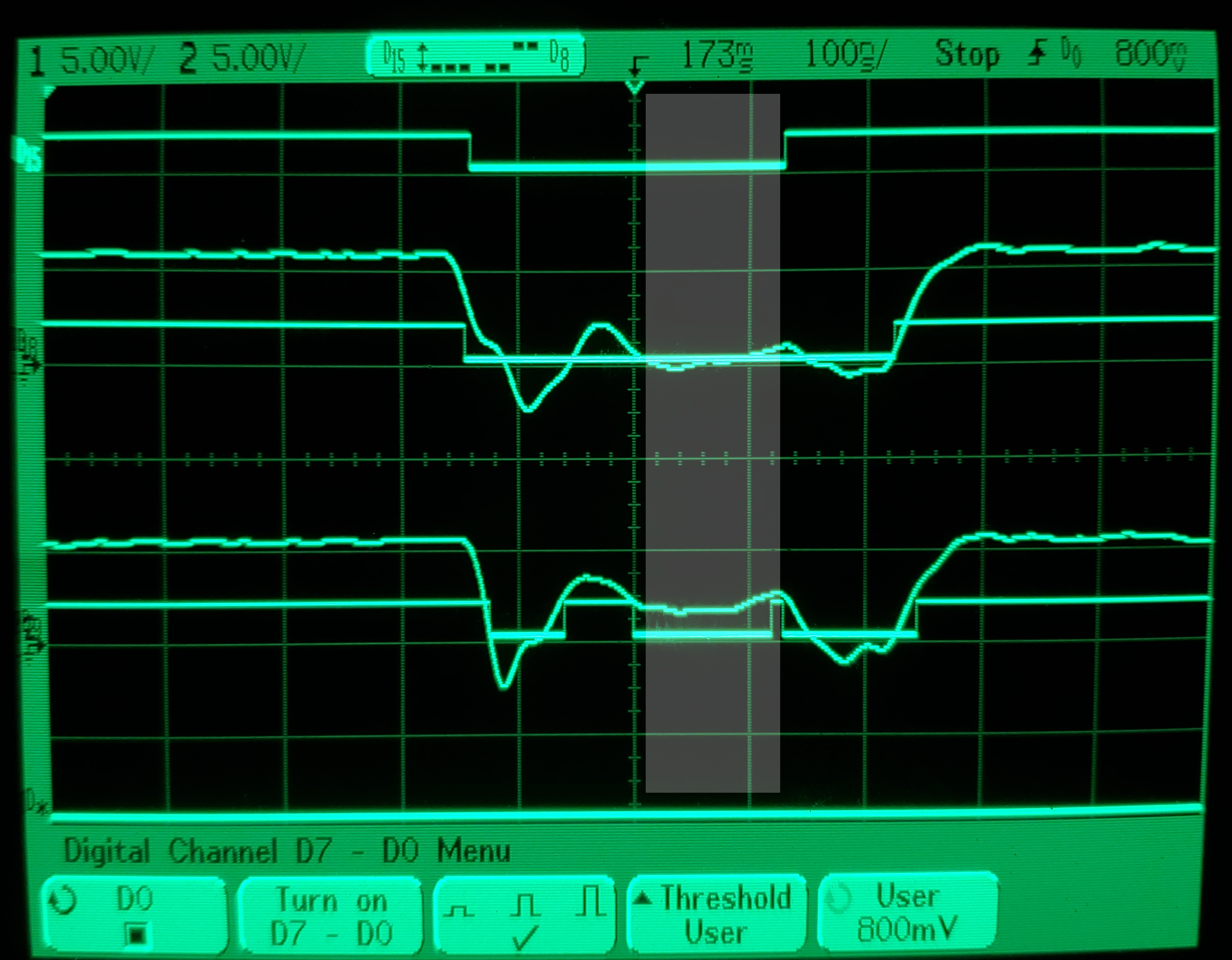
Both 1/0 and 0/1 cases are no longer. In Case C, D4 is pulled up so far by A2 that it no longer reads as a 0. In Case D, A2 is pulled down so far by D4 that it no longer reads as a 1.
This simple change can cause a drastic effect on the program and the sound. Even a single unexpected bit can cause the program to fly off the rails. Importantly, this is still totally deterministic: the program will be different the same way each time. 'Warbling' the synth ROM is essentially reprogramming it without control over what it's programmed to. The result is a kind of mystery-mode-machine!
Hope you enjoyed reading!