DX7 Keyboard Controller and Digital Sequencer for the Casio MT-240
March 14, 2026
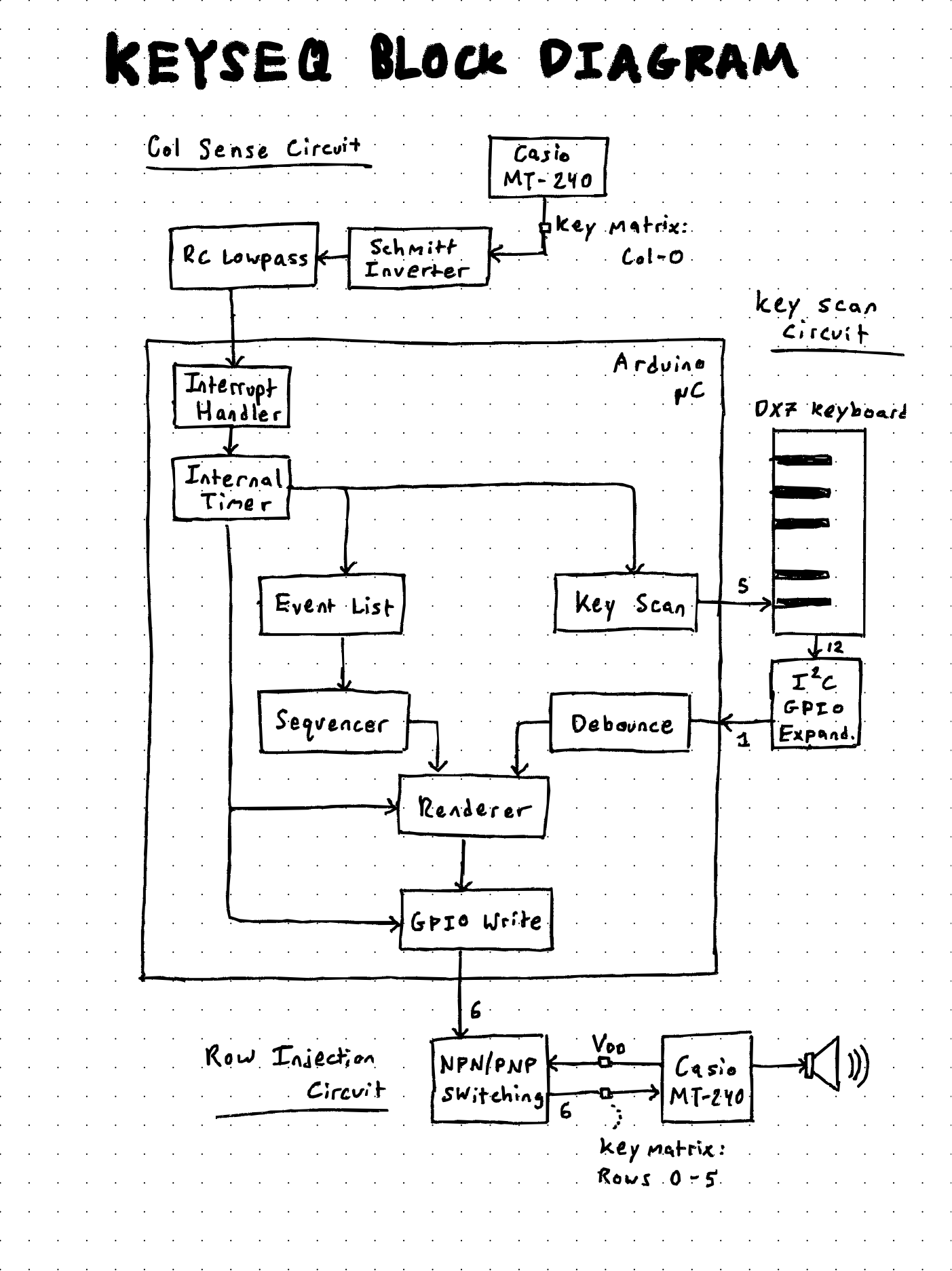
This controller is both a keyboard and digital sequencer. By sensing the MT240 key-scan cycle and injecting a precisely timed pulse, the physical contact behavior of the MT240 keyboard matrix can be emulated with software running on an Arduino microcontroller. The user can input notes via a keyboard repurposed from a Yamaha DX7, and/or by programming a sequencer.
Sensing and injecting into the MT-240 keyscan cycle
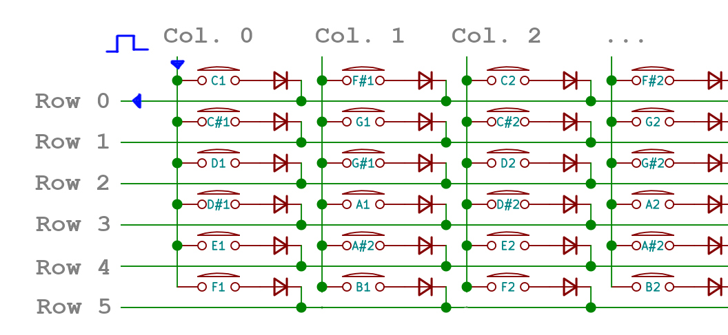
Keyboards, both musical and computer, work by organizing their keys into a grid. The CPU scans the grid by sending a pulse down its columns, one at a time, and seeing which rows the pulse ends up at. If a key is pressed down, the pulse is able to travel from column to row, and the computer knows that a specific column-and-row pair corresponds to a specific note.
Another way to think about it is that Every key has its own specific column timing and row position. For example, in the image: Column 0, Row 0 corresponds to the key C1. This means that in order for the CPU to register this note, it must detect a pulse on its Row 0 detector at the time Column 0 is pulsed.
If we know when a column pulse happens, we can inject our own pulse into a row. If we know when the Casio is pulsing Column 0, we can inject our own pulse into Row 0 and the Casio will see that as a valid press of the key C1.
Detecting column zero
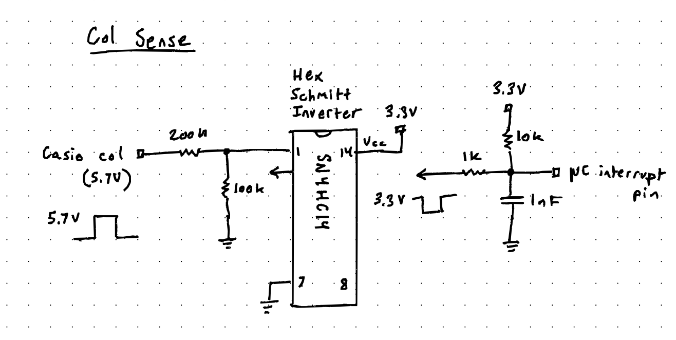
The circuit used to detect Column 0 uses a voltage divider to bring the 5.75 V rising-edge pulse down to 3.3 V. Then, a Schmitt trigger cleans and inverts the signal to a falling edge. It is then passed through an RC low-pass filter before reaching the microcontroller GPIO pin, where it triggers an interrupt in the code. The filter prevents EMI pickup from leading to false-positive interrupts.
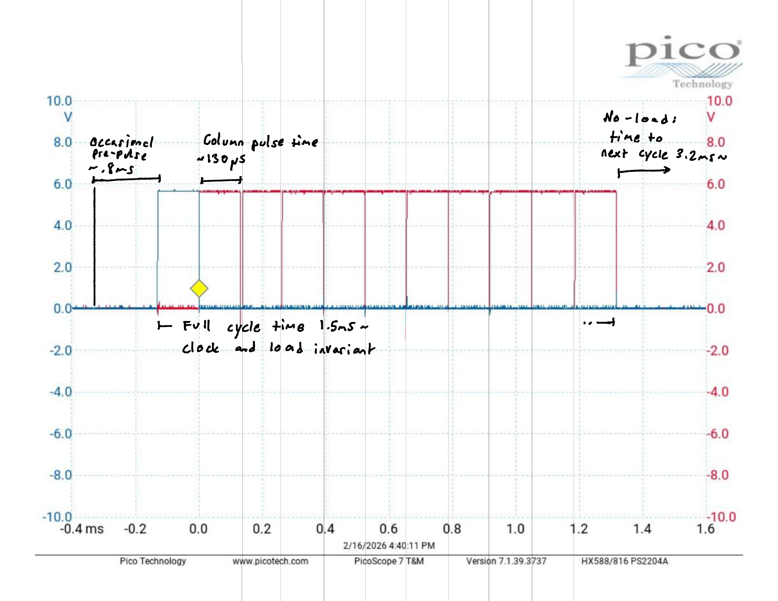
Casio fortunately made the column-pulse cycle pretty deterministic. The oscilloscope image below is a superimposition of all 11 column pulses. First, note how each column pulse is the same width and that there is no overlap between pulses. Second, note that there are 11 pulses, and then the cycle ends.
Because the pulses are regular and equal in width, about 132 microseconds, I decided to detect the rising edge of the first pulse, Column 0, and use it as the timing reference frame for the rest of the cycle. Now we know that Column 5 happens at 132 microseconds × 5 = 660 microseconds, relative to Column 0.
Rendering a keyscan frame
There is plenty of time to compute and inject data for all the other columns, but for Column 0 itself there needs to be minimal delay between interrupt and row injection. We need to arm Column 0’s row data in advance so that it can simply fire upon interrupt.
The problem can be solved if we precompute an entire frame, six bits of row data for eleven columns, during the off-cycle time between key scans. The idea is to render the frame suring the off-cycle, so that it can simply be fired off one byte at a time at every column timing interval.
Row injection circuit
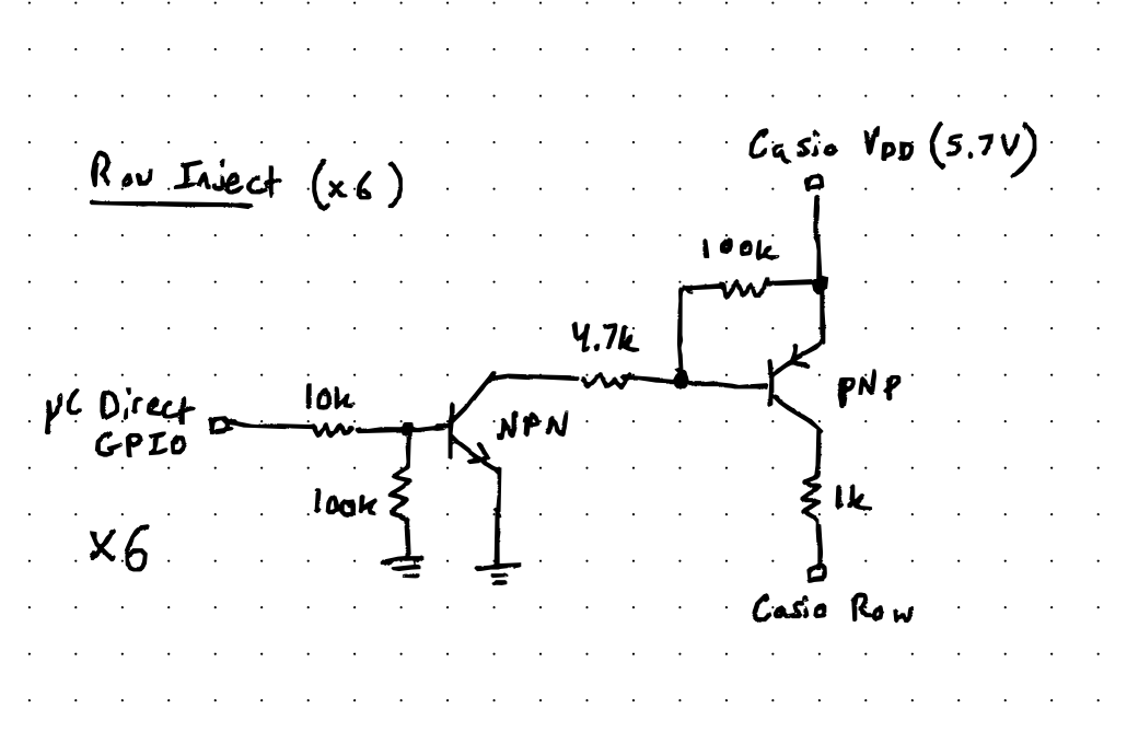
When a note is played on the original MT240 keyboard, the column is physically contacting the row. Since the column pulses are at 5.75 V, the MT240 is expecting to see the same approximate voltage on its row detectors. The challenge is that the microcontroller can only output 3.3 V, but it needs a way to pull a row up to about 5.75 V.
The NPN / PNP switching circuit above was used to accomplish this. The NPN is normally pulled low. The PNP is normally pulled high to 5.75 V. When the microcontroller asserts a row, it turns the NPN on by pulling its base high, which turns the PNP on by pulling its base low, causing the 5.75 V pulse to appear at the row. Thankfully, the saturation recovery time is not too long to interfere with the timing.
Repurposed DX7 keyboard
Now we need a way to input note data. One way is with another keyboard, one with its own separate column-and-row matrix.
During the off-cycle time, the microcontroller pulses each column of the keyboard, detects which rows the pulse appears on, and correlates that to a note in software. The note is then debounced and sent to the renderer. This is exactly the same general method the Casio MT240 is also using.
But why hijack the MT240 key matrix if we are just going to emulate it with another key matrix? The advantage is that a microcontroller now intercepts the keyboard, allowing notes to be manipulated in software. For example, an individual-note sustain mode can be implemented easily by programming key-press and key-release events to occur on alternating key strokes.
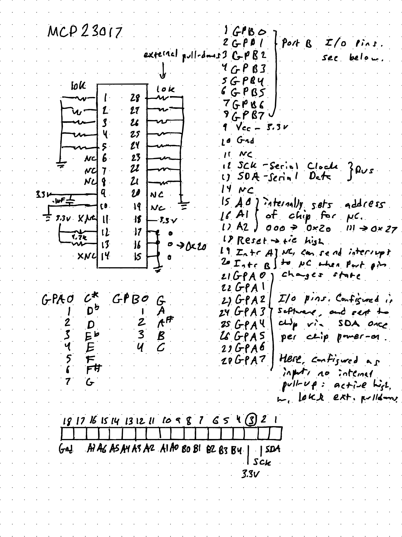
The DX7 keyboard also feels much nicer to the fingers. The only issue with using a non-Casio keyboard was that Yamaha organized its key matrix differently, 5 × 13 instead of the MT240 arrangement. In order to save on pin counts, an I2C GPIO expander was used to shift the 13 row inputs serially to the microcontroller on one pin.
Sequencer for the Casio MT240
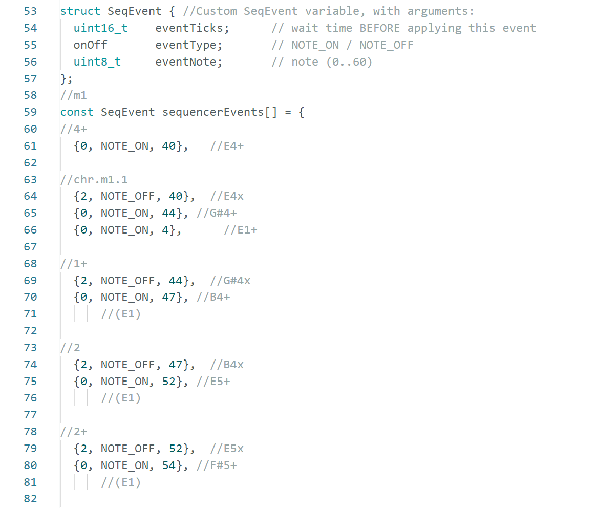
Building a software sequencer with the scan-cycle and renderer already in place was pretty straightforward. Instead of an external input creating key-press and key-release events, an internal list of events can be pre-programmed in software.
The advantage of this is that events can be timed to the frame. This means the system can do things that are not humanly possible, such as play a note for a single frame or play a rapid succession of notes with tightly controlled timing. It can also program full songs consisting of notes with rhythmic durations.
Alternative keyboard modes
By changing how the sequencer and keyboard input methods interact, the keyboard interface can be played in a variety of modes. In addition to normal keyboard mode, some ideas include:
- Individual key latch mode
- Shortest-possible note mode
- Infinite sustain mode
- Rapid hammer mode
- Hammer envelope
- Explode mode (demonstrated in audio clip above)
- Note remapping
- Arpeggiator
- Vocoder (possibly, with DSP)
- Record note to playback
- Mapping keys to functions
- Controlling two synths with the same keyboard
The last item, controlling two synths, has been a long-term goal for Cryptwarbler. Dual Casio MT240s would enable a lot of things, such as overlapping textures, quadraphonic output, easing transitions with a dj-style fader, and interlocking drum-machine rhythms done by syncing the two clocks.
Mapping keys to functions would also be fun and very useful. The keyboard can be thought of as an array of 61 buttons, so in a hypothetical function mode, playing a C#7add11 chord could make Für Elise play at 16× speed.
Known problems, potential solutions
- The timing of the row injections is synced to a specific Hartley oscillator frequency. The MT240 uses a Hartley oscillator to set the pitches of notes and, apparently, the period between column scans as well. Manipulating the Hartley oscillator frequency can lead to really nice slow-tape-speed-like warbly effects, so it would be good to make that compatible with the keyboard-sequencer. Proposed solution: each column triggers its own row injection, instead of using a timer-based cycle synced to Column 0.
- Tempo of sequenced notes is variable based on the TONE preset. Something I did not anticipate was that each of the TONE presets, such as Piano or Flute, has a different amount of off-cycle time between key scans, probably because each tone takes a different amount of CPU time to synthesize. This means that the tempo of notes played on the sequencer, which increments each time the cycle completes, is different for each TONE preset. Proposed solution: an external timer increments the sequencer, with the option of syncing to the key-scan cycle.