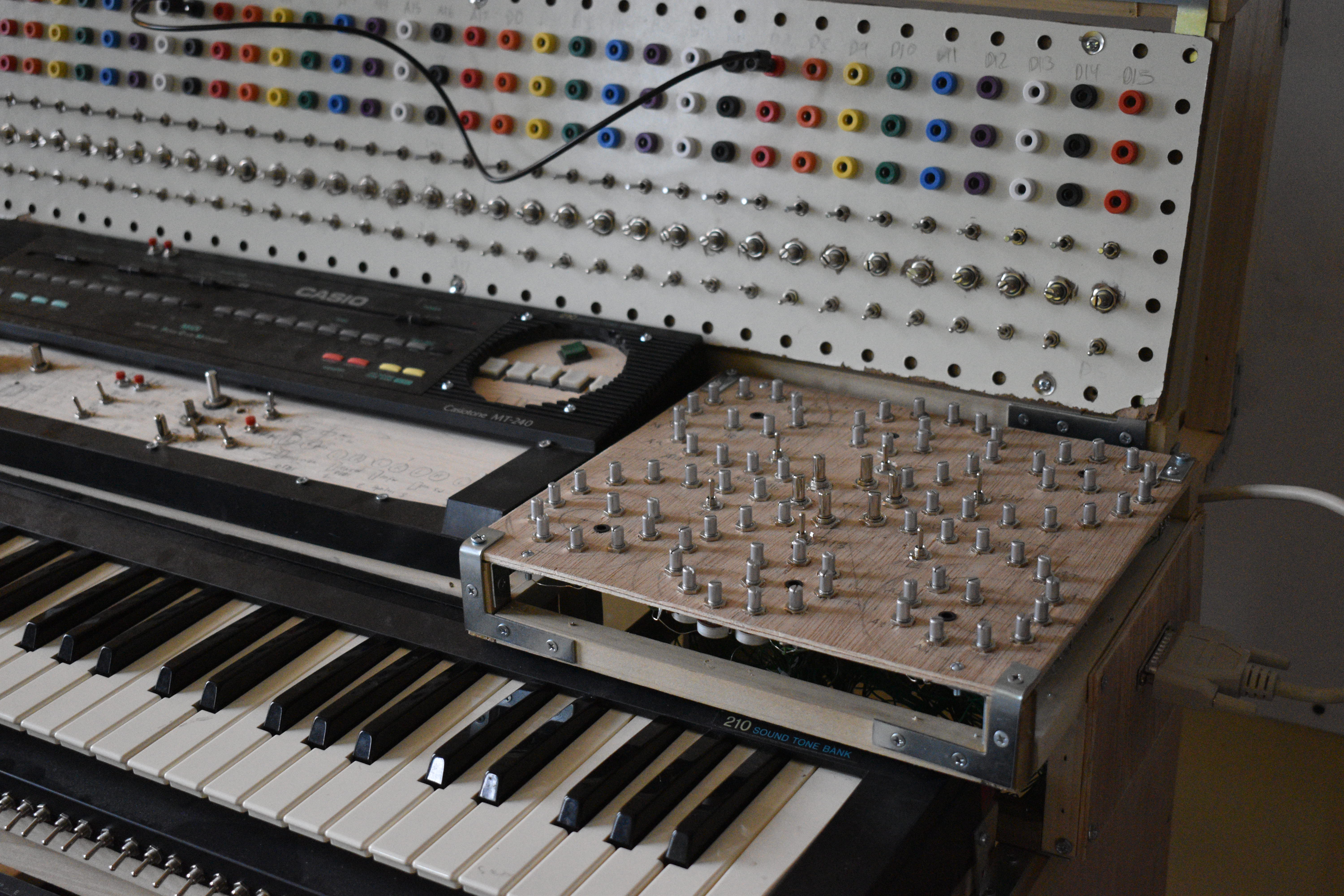
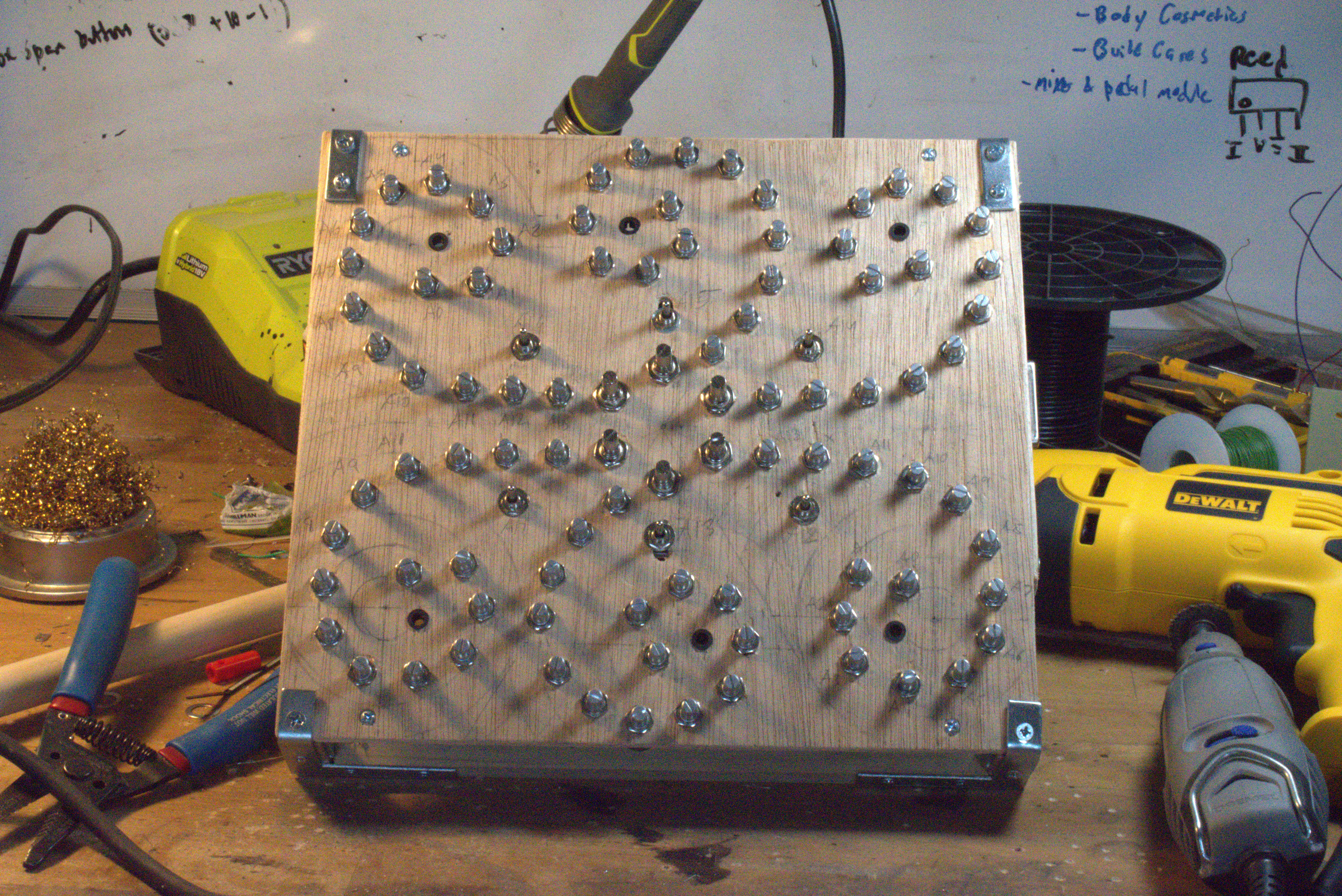
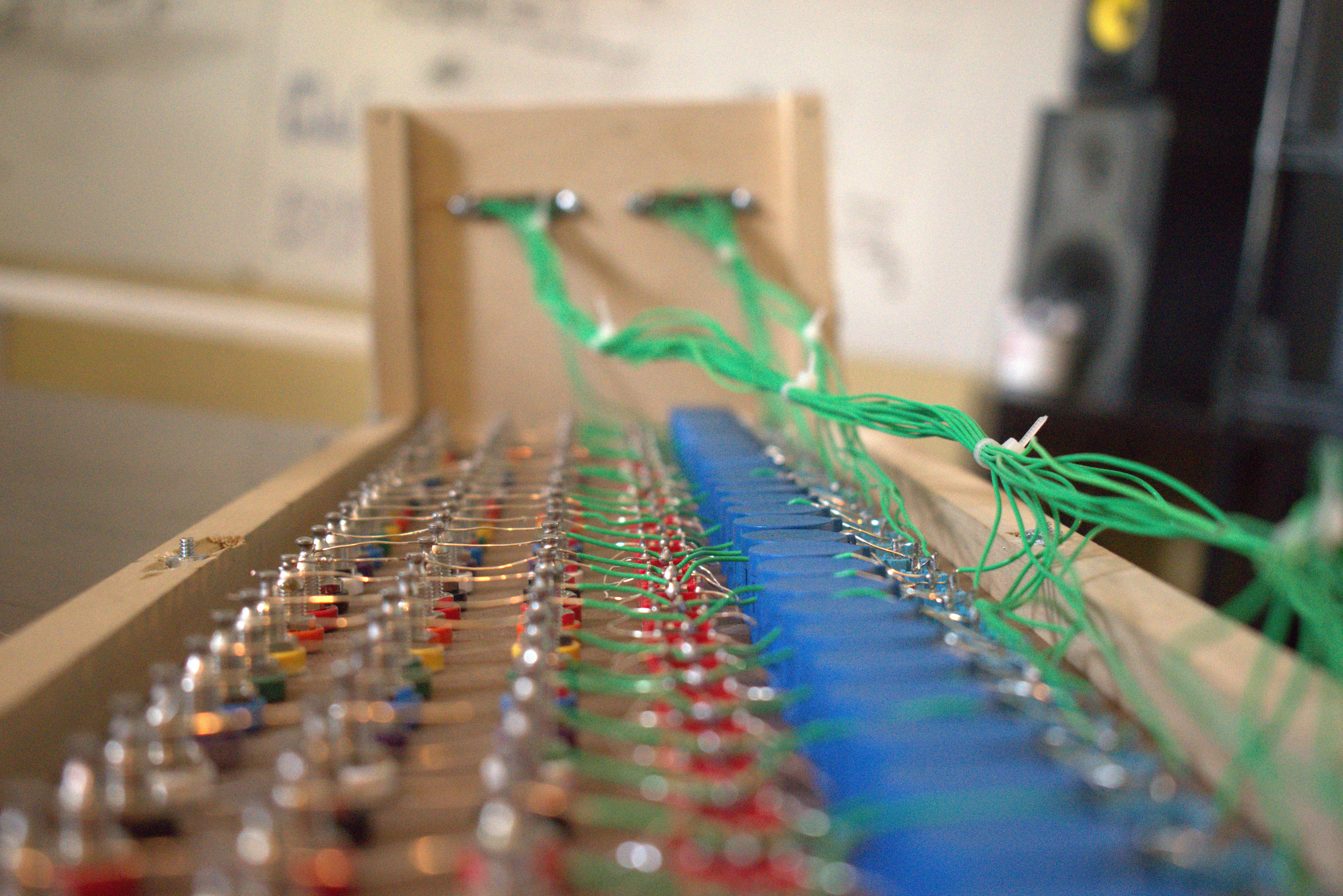
Greater control over timbre of preset-TONES (piano, flute) along six spiral arms. Stable or unstable modes.
There are six spiral arms, each with 15 knobs and one control switch. The switch toggles the spiral arm between two modes: 1. Timbre Mode (down position) or 2. Crazy Mode (up position).
In Timbre Mode, the spiral arm's switch is in the down position. All the knobs on that spiral are now readied. In its CW-most position, the knob is inactive, and no change to the timbre can be heard. Turning a knob CCW past a threshold activates it, passively changing the timbre. The outermost knob, labeled "A0", controls the highest frequency timbre, and the frequency controlled gets lower with each knob. The innermost knobs, ending with "A13", control a frequency perceived as rhythm instead of pitch. The larger 15th knob overrides the other 14.
Spirals A14-17 (the top three spirals plus A17) are passive, meaning you can play the keyboard like normal while Timbre Mode acts passively. Spirals A12 & 13, are active- playing notes on the keyboard will only output glitch. These two spirals can be used in Timbre Mode to affect sounds already being produced; for example, you can play sustained notes on the keyboard, then change the timbre.
Not all of the four passive spirals will have an audible effect, depending on the active 'TONE preset' (ie Piano, Flute). For example, 'Vibraphone' only has an audible timbre change with spirals A14 & A16; using Timbre Mode on spiral A15 won't sound any different. The TONE-Spiral compatibility is shown in this table: [table]
In Crazy Mode, the spiral arm's switch is in the up position. In its CW-most position, the knob is inactive, and there is no effect. Turning a knob CCW past the Crazy Threshold activates a 'crazy' effect on the sound: samples change timbre and start cycling weirdly. Turning the knob even further, activates a 'frozen' effect on the sound: the cycle gets stuck on a small section. It's possible to ride between these two effects, causing samples to go crazy or freeze randomly. The larger 15th knob, which is a ten-turn pot, is useful for straddling these two effects. This mode is not keyboard compatible.
A fun way to make full use of the controller is to first capture a sample in a Crazy Mode spiral, then use Timbre Mode on the other spirals to change the timbre while it's going crazy. Using Crazy Mode on multiple spirals simultaneously, the sound jumps between textures and timbres as loops freeze and cycle wildly.
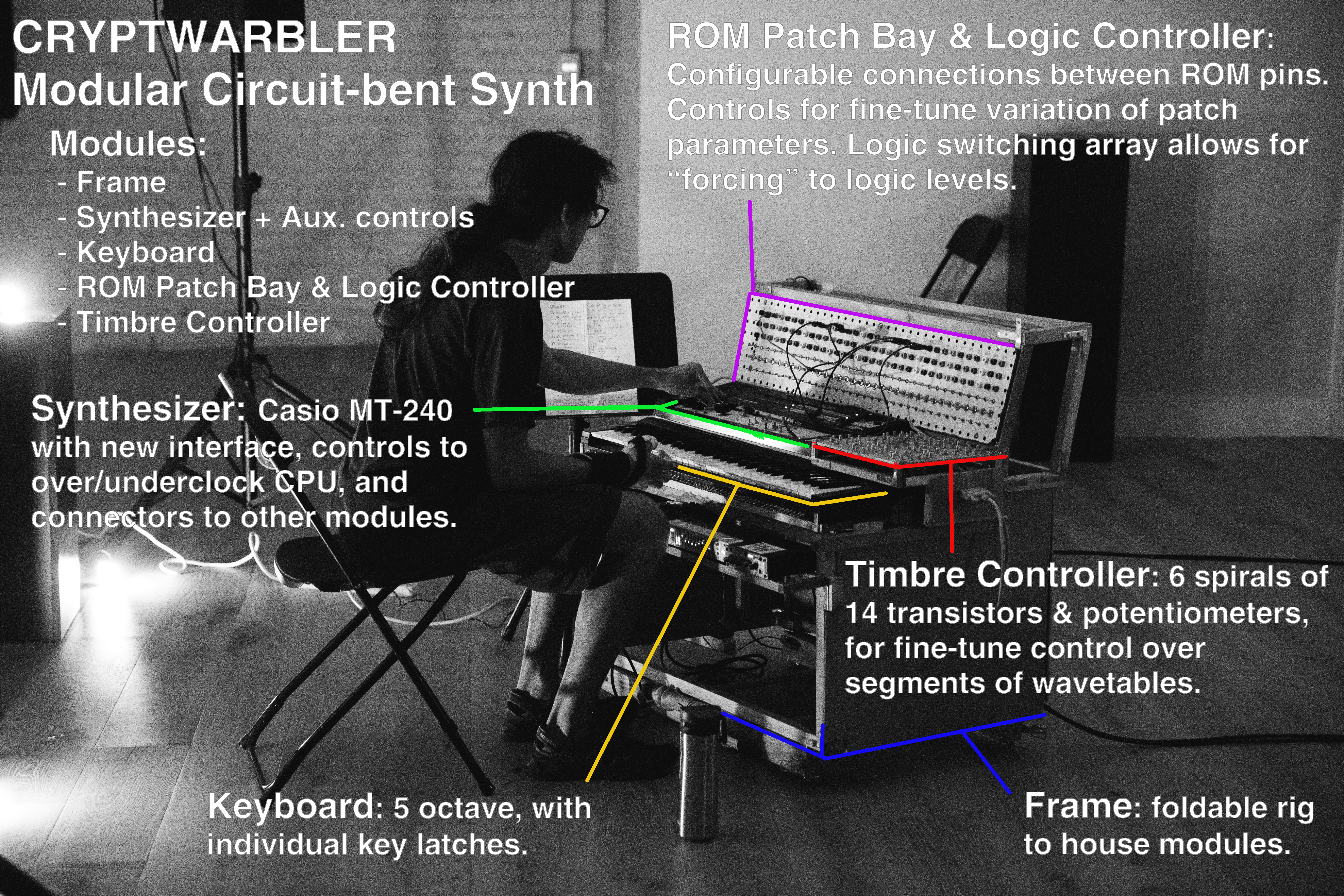
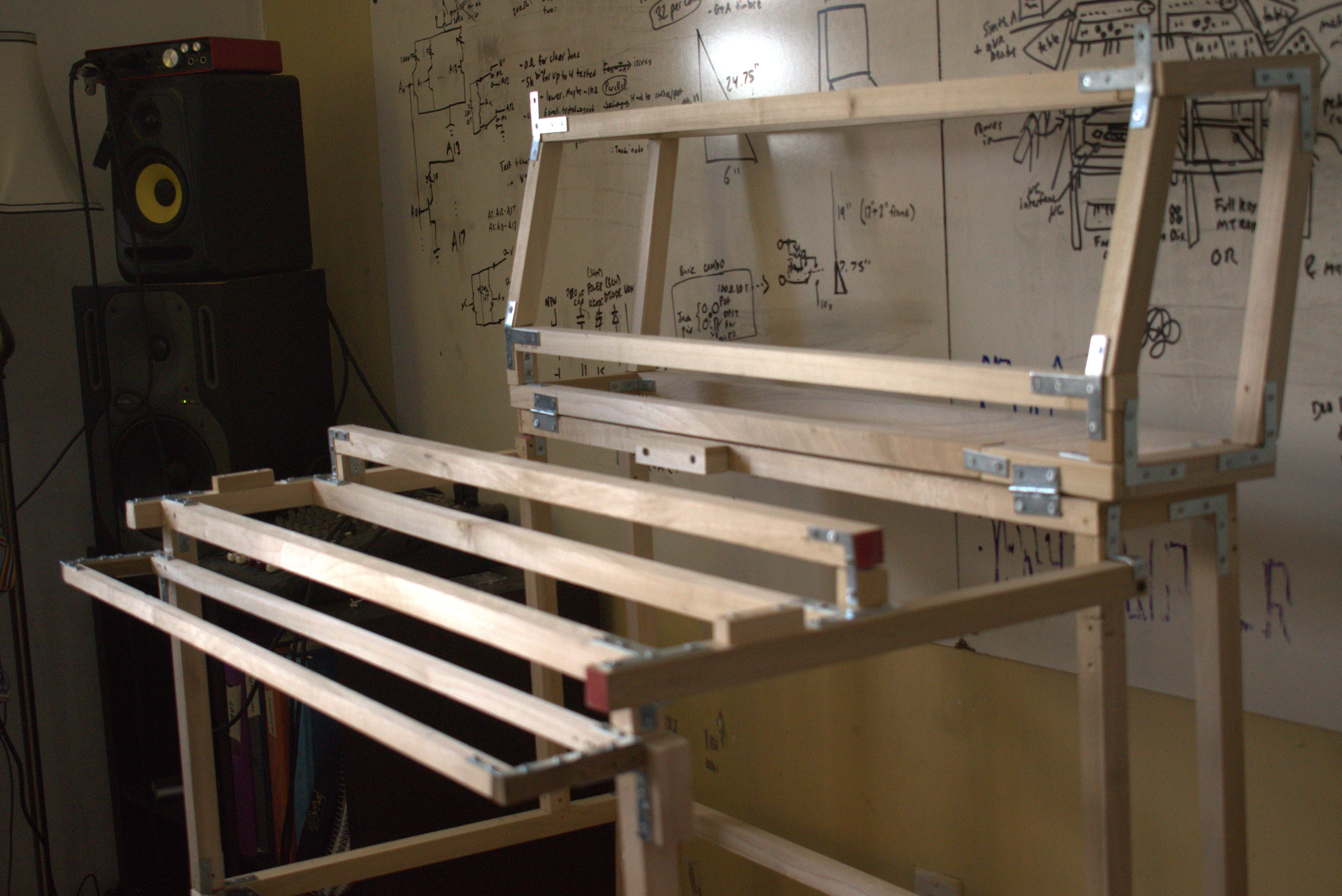
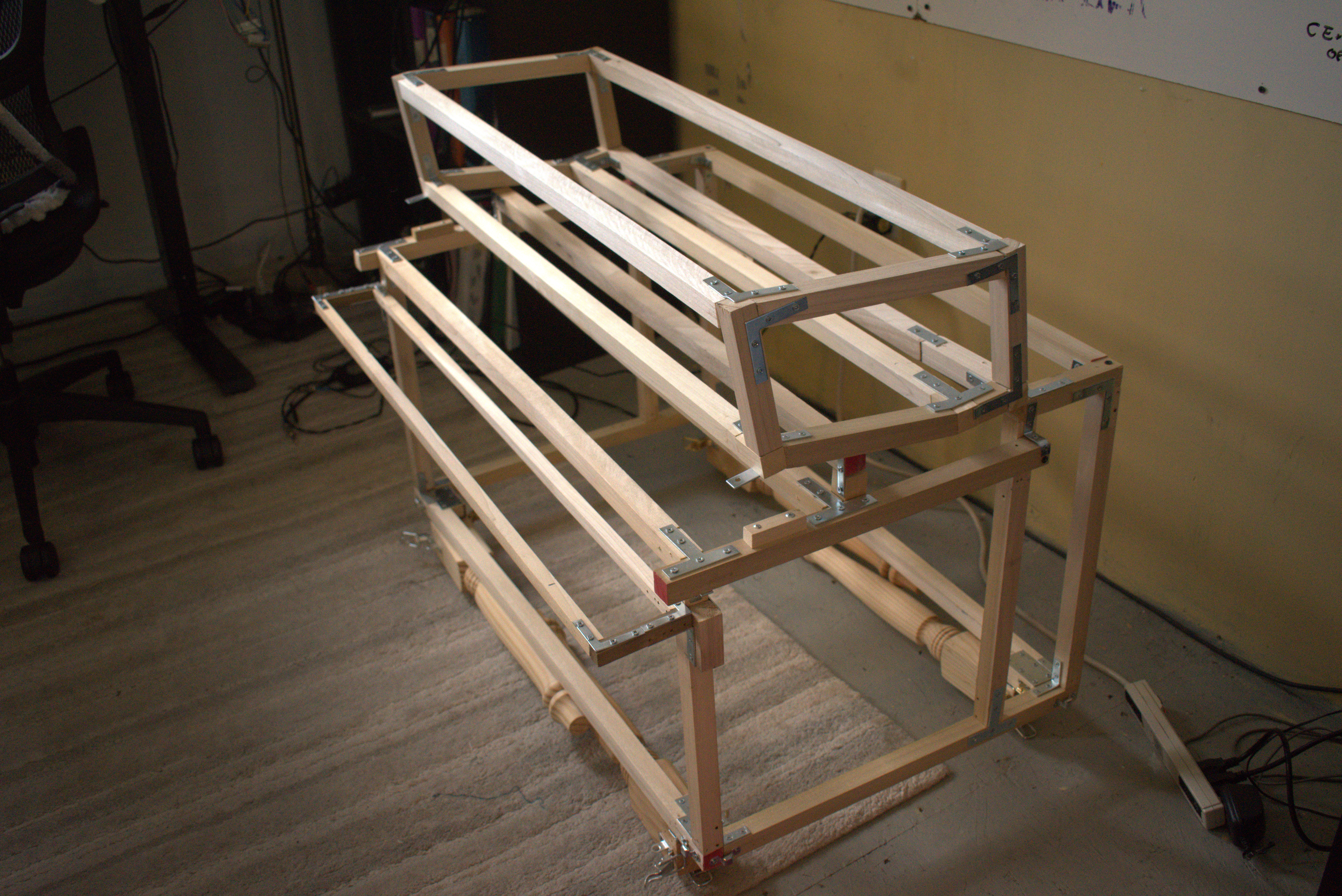
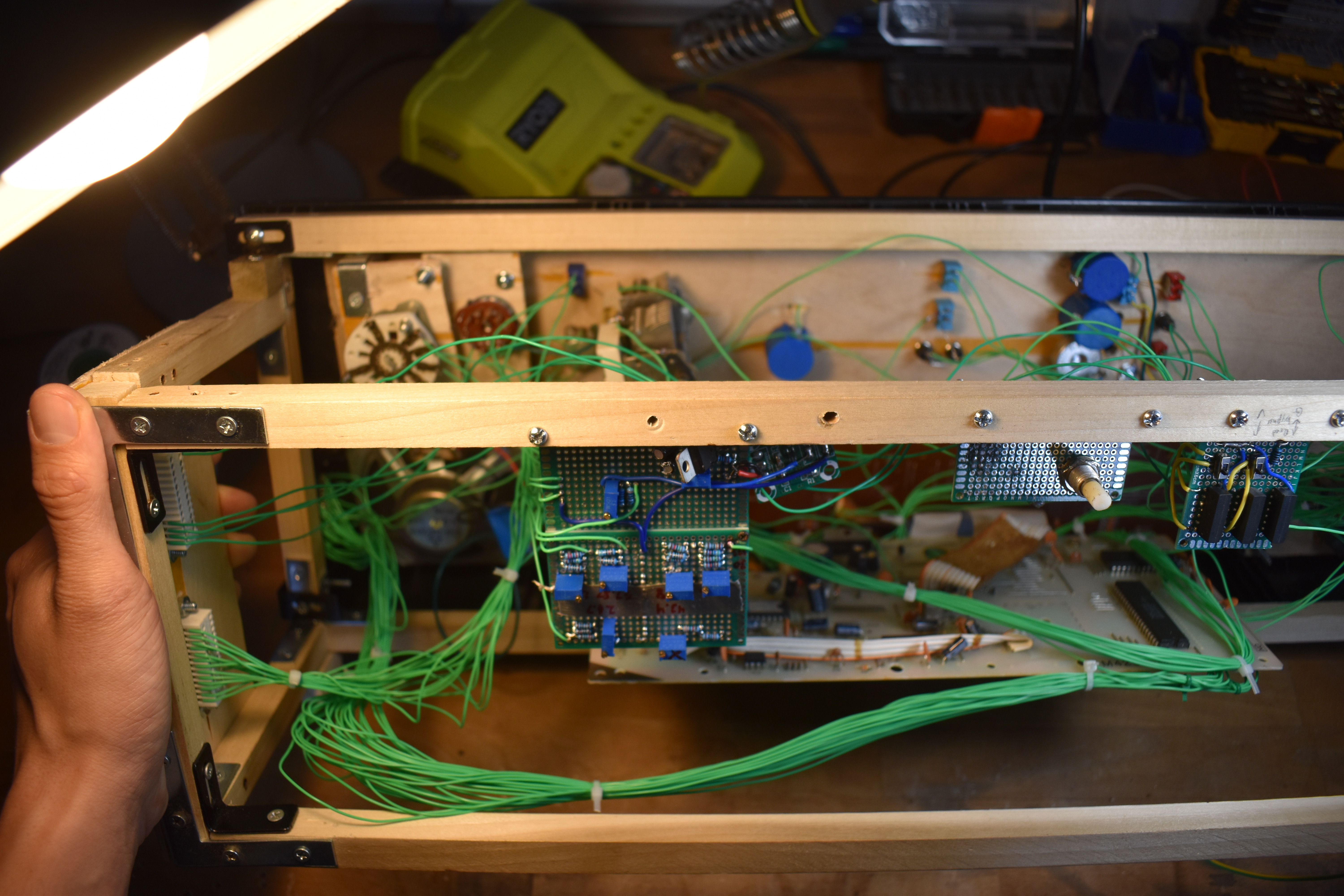
The Frame recieved some major updates in April. It is now as deep (20") and as tall (32", folded up) as it can be, while still fitting in my friend's bus. The legs are reattached, now with hinges that allow it to fold in, kind of like a camel sitting down. Additionally, the rig for the ROM Logic Bay also folds over the top.
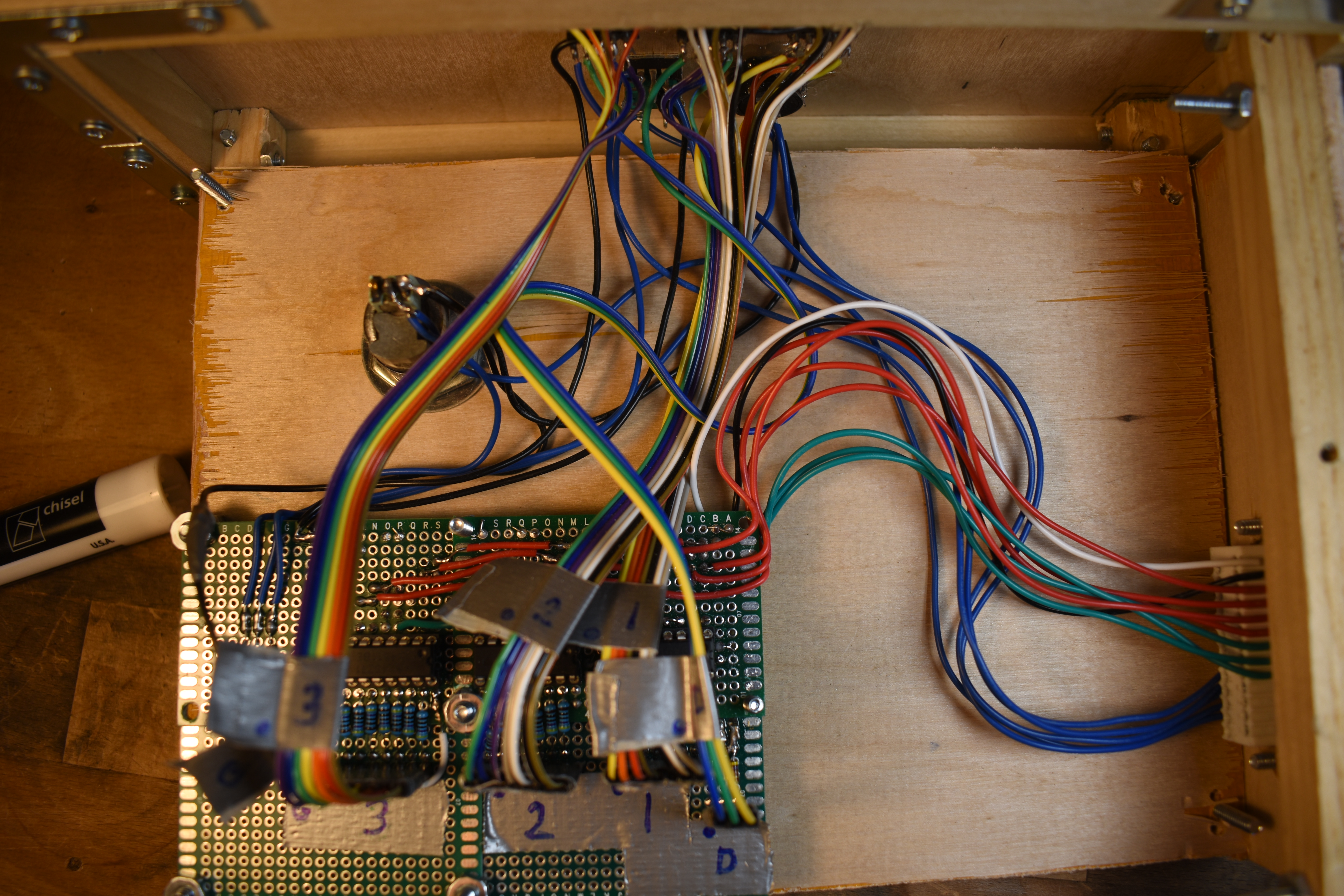
The ROM Patch Bay/Logic Controller. Each ROM pin is broken out to a column on the controller. Each column has six components. The top three are the ROM Patch Bay. Banana jacks let ROM pins get patched together using banana cables. The bottom three are the Logic Controller. An on-off-on switch lets one connect a ROM pin to either V+ or Gnd, forcing it to a logic 1 or 0. The 200 ohm 10 turn Pot allows for analog tweening between the digital logic levels, as well as allow for "tuning" of patches on the Patch Bay (some patches need between 0-400 ohms resistance). The bottom switch is a bypass of the Pot for quick switching.
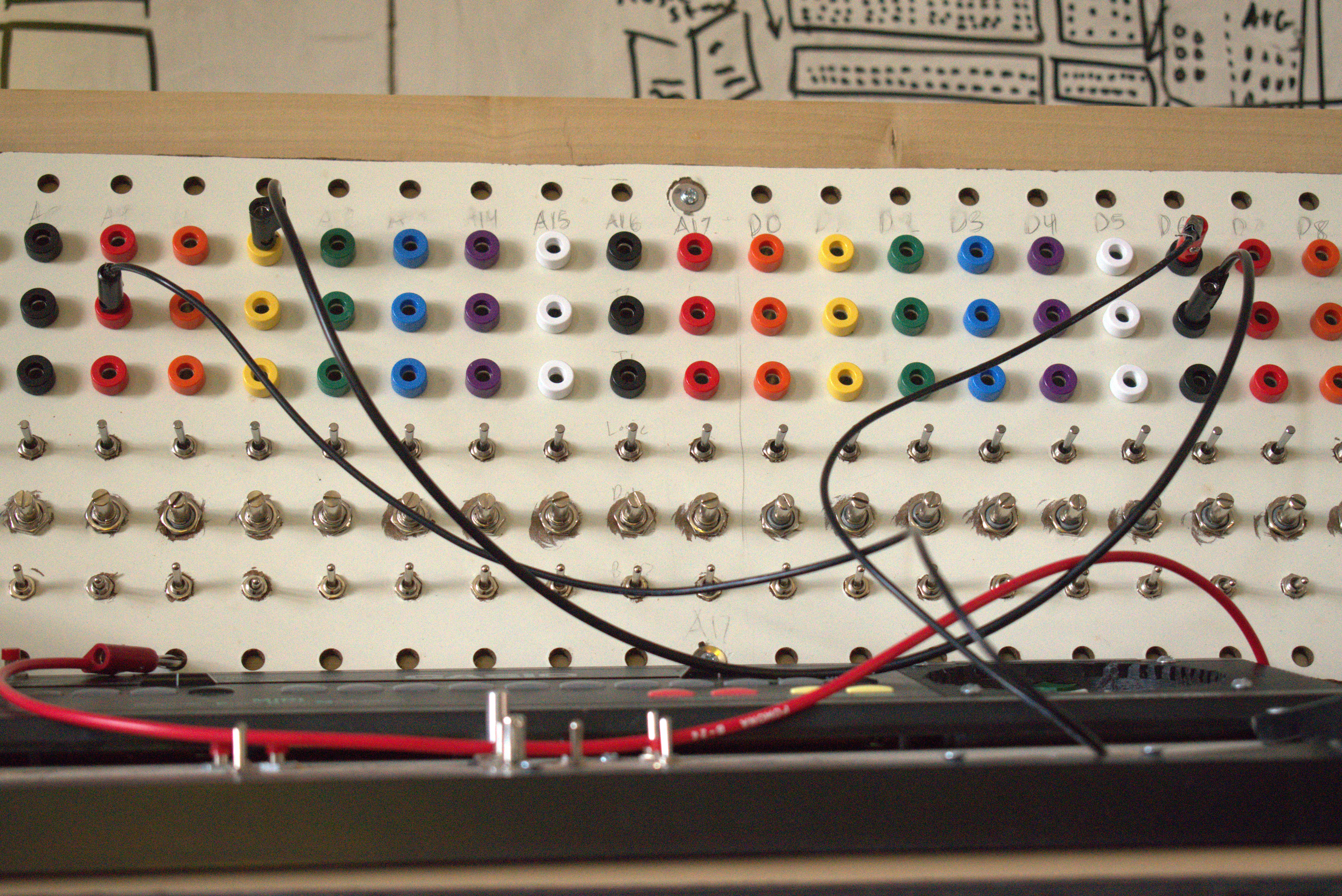
todo:
- add LEDs for logic indicators
- make it look nicer
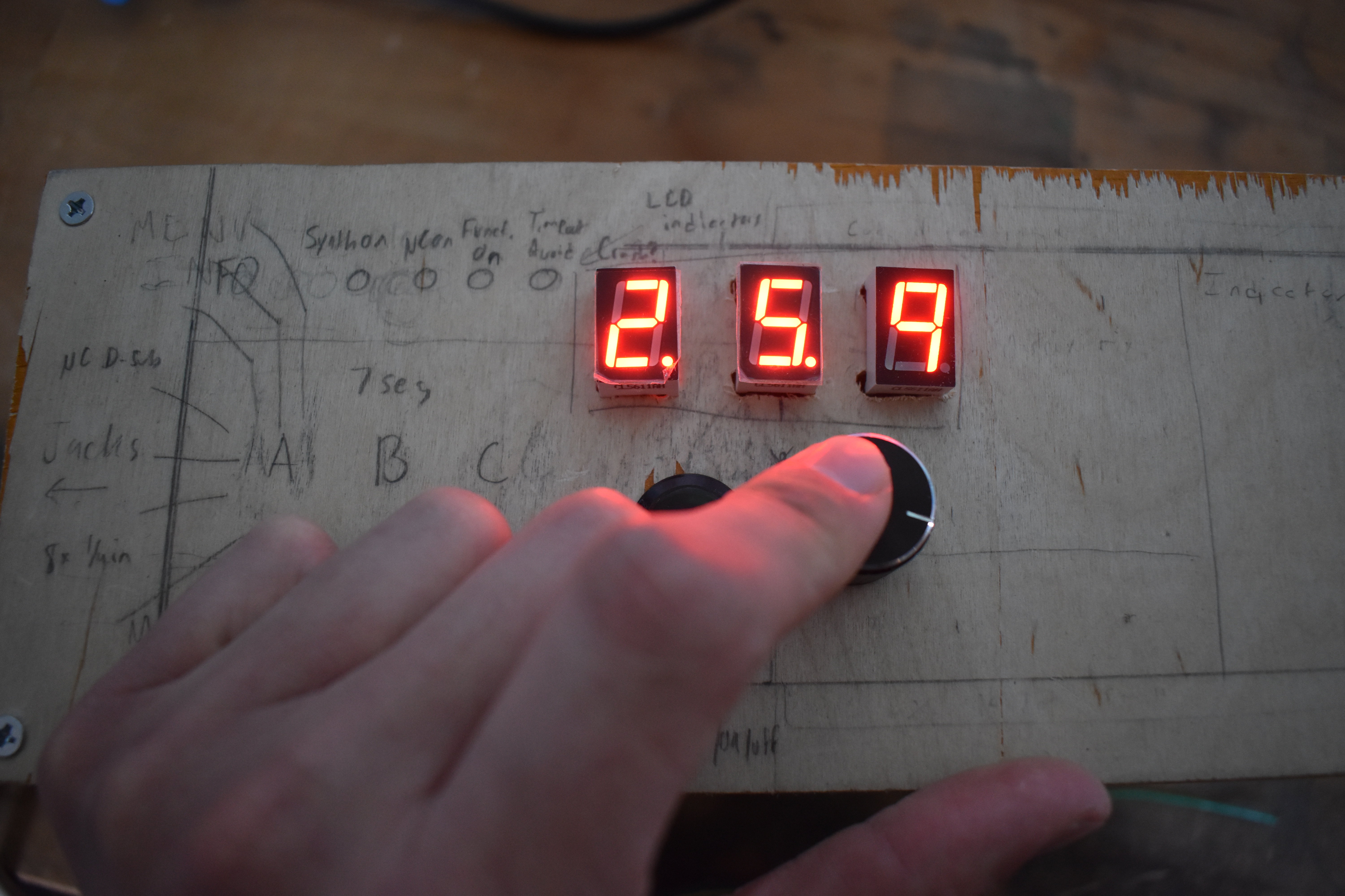
A menu interface with a rotary dial, select, return buttons to choose a uC function. The idea is, for example: 5 => LC pitch circuit; 5.7 => LC tremolo circuit; 5.7.9 => fastest tremolo speed, send. I think it'll also be a good framework for programming the microcontroller.
to do:
- add indicator LEDs (indicates when critical things are functioning)
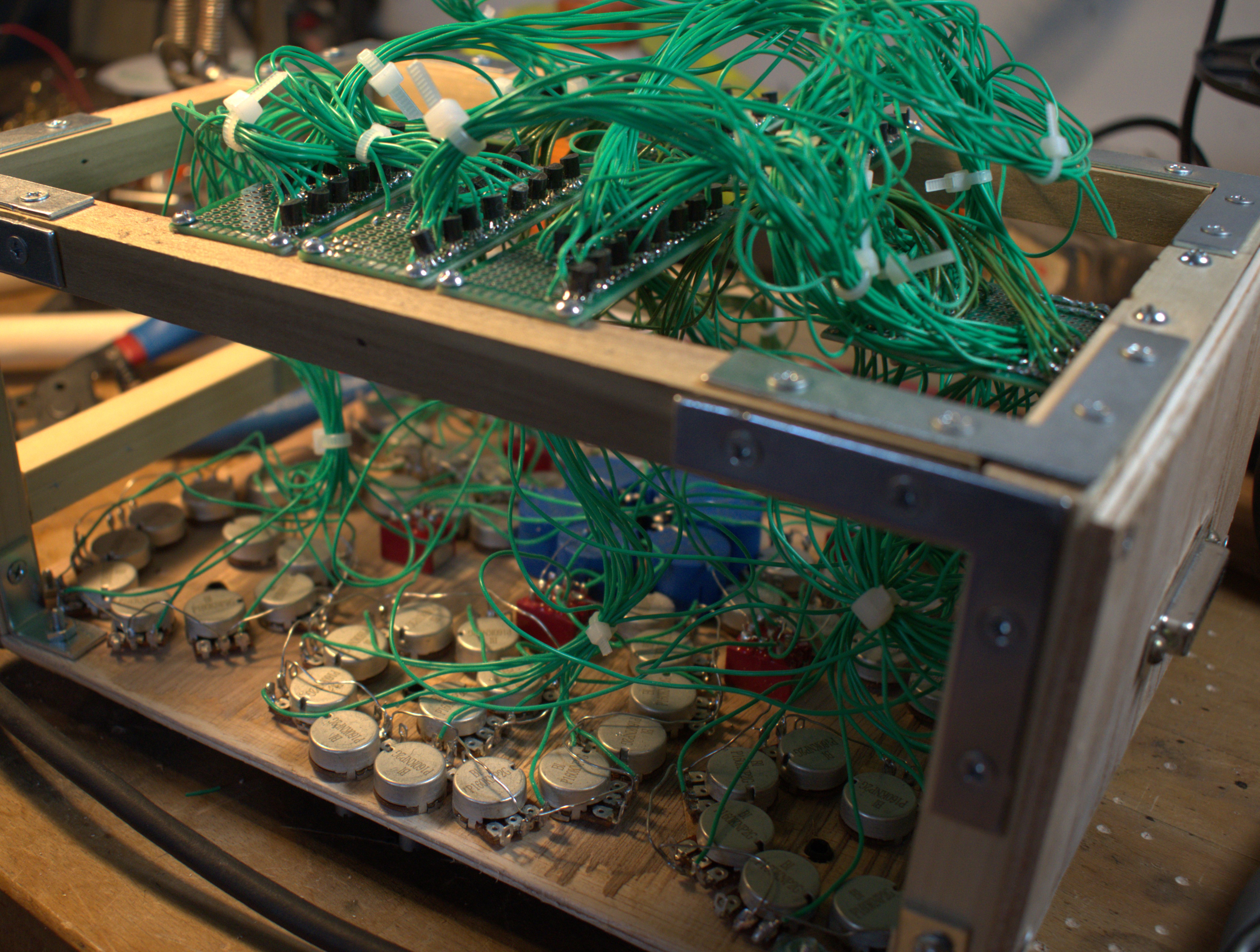
This is the Synth Body, with the original main MT-240 circuit board. I've removed the back and made the board vertical so I can access it easier. The body is also home to all auxiliary bends. The controls for these are where the original keyboard used to be, and the circuits are mounted on the bottom.
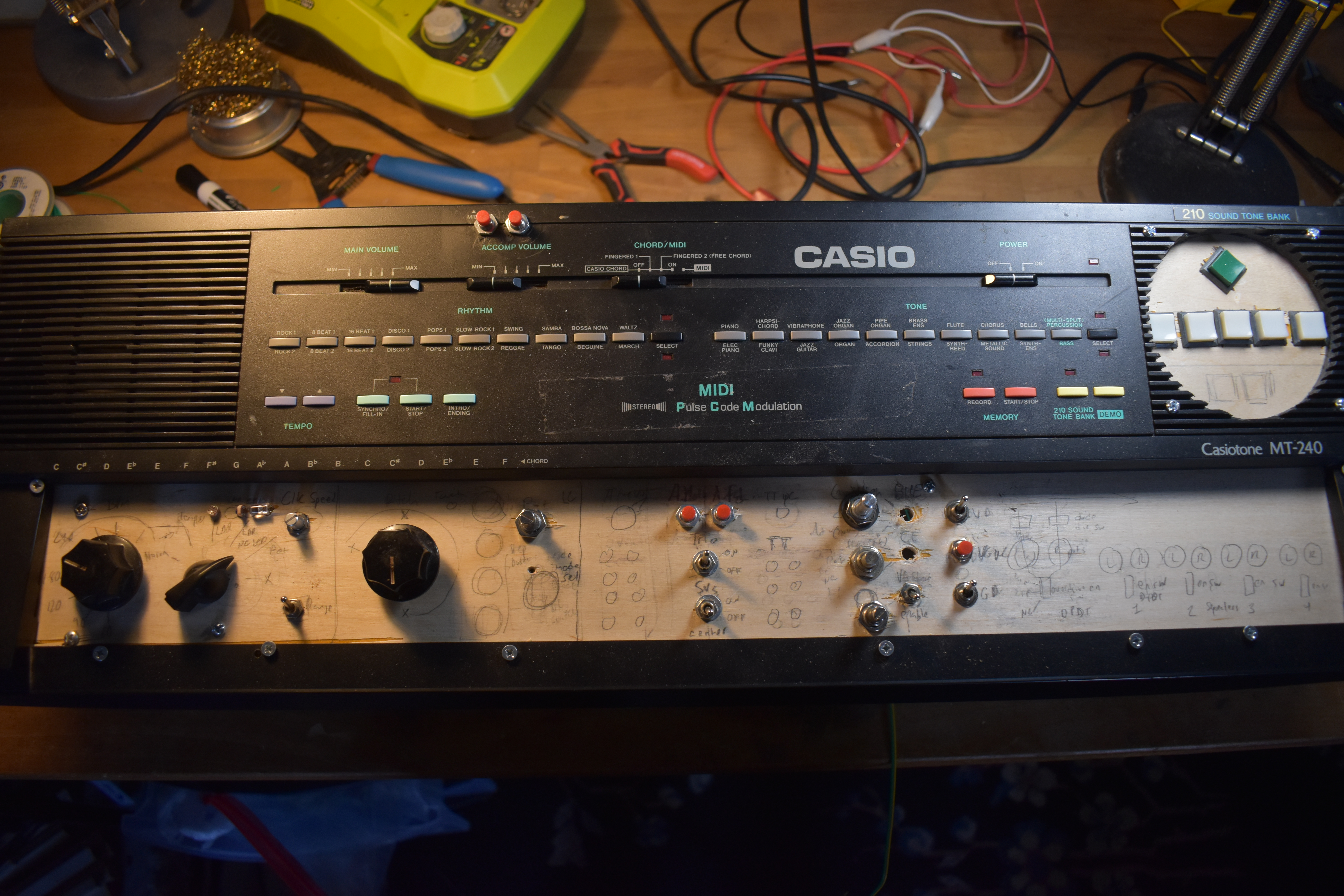
The aux. bends circuit can be broken down into a couple of smaller circuits:
- Clock circuit
- LC pitch circuit
- Hidden functions
- ROM dysregulate and disengage
- DAC overdrive & squealers
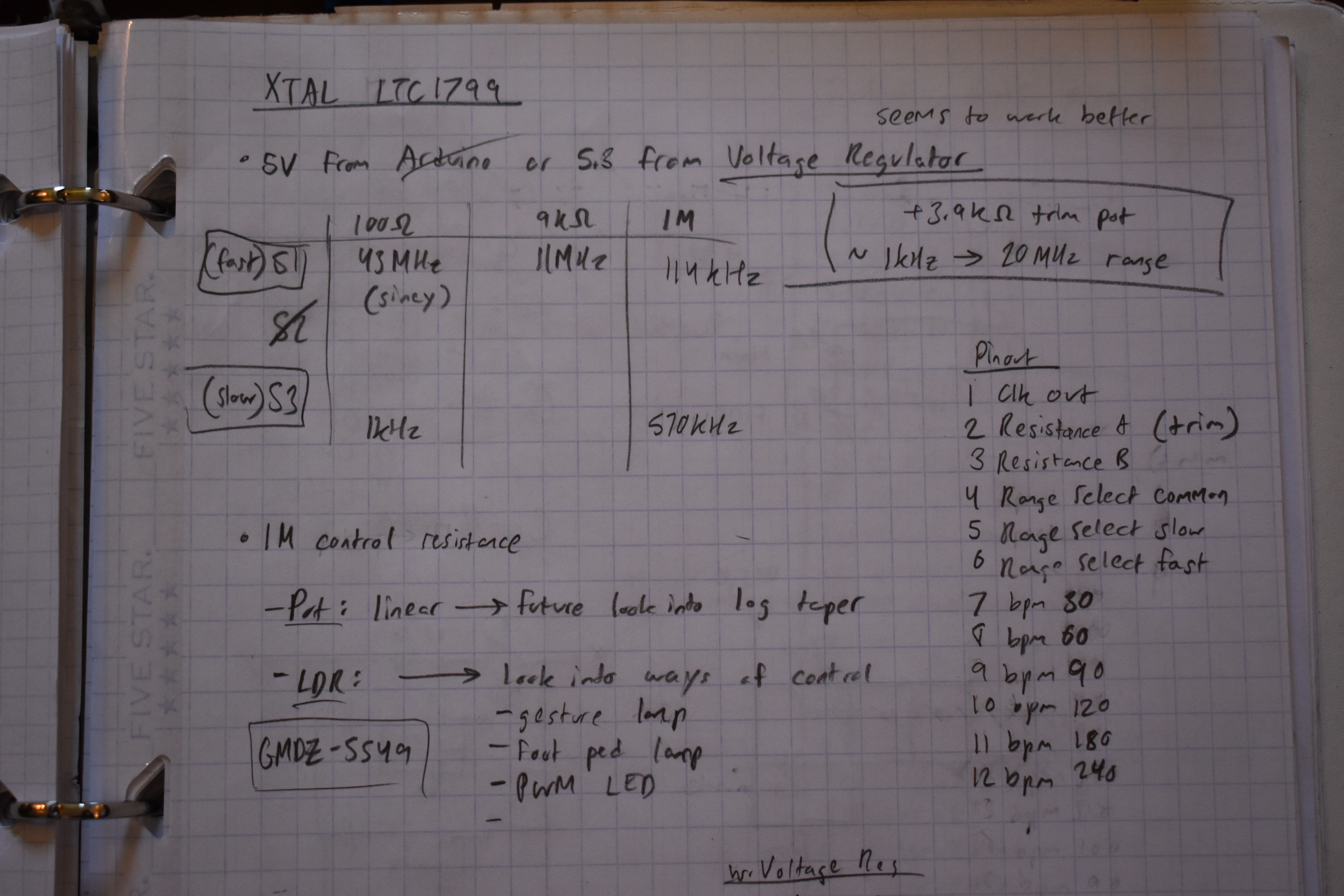
The clock is powered by an external ltc1799 squarewave oscillator chip. The speed of the oscillator is currently controlled by a resistance up to 1M. A rotary dial is used to select between modes: potentiometer, ldr, or steps (controlled by another rotary dial). A switch controls the range of the potentiometer.
todo:
- Try uC pulsing an LED
- chain two Casio MT-240s controlled by same clock
- far future: divide the frequency to have clk speed ratios between synths
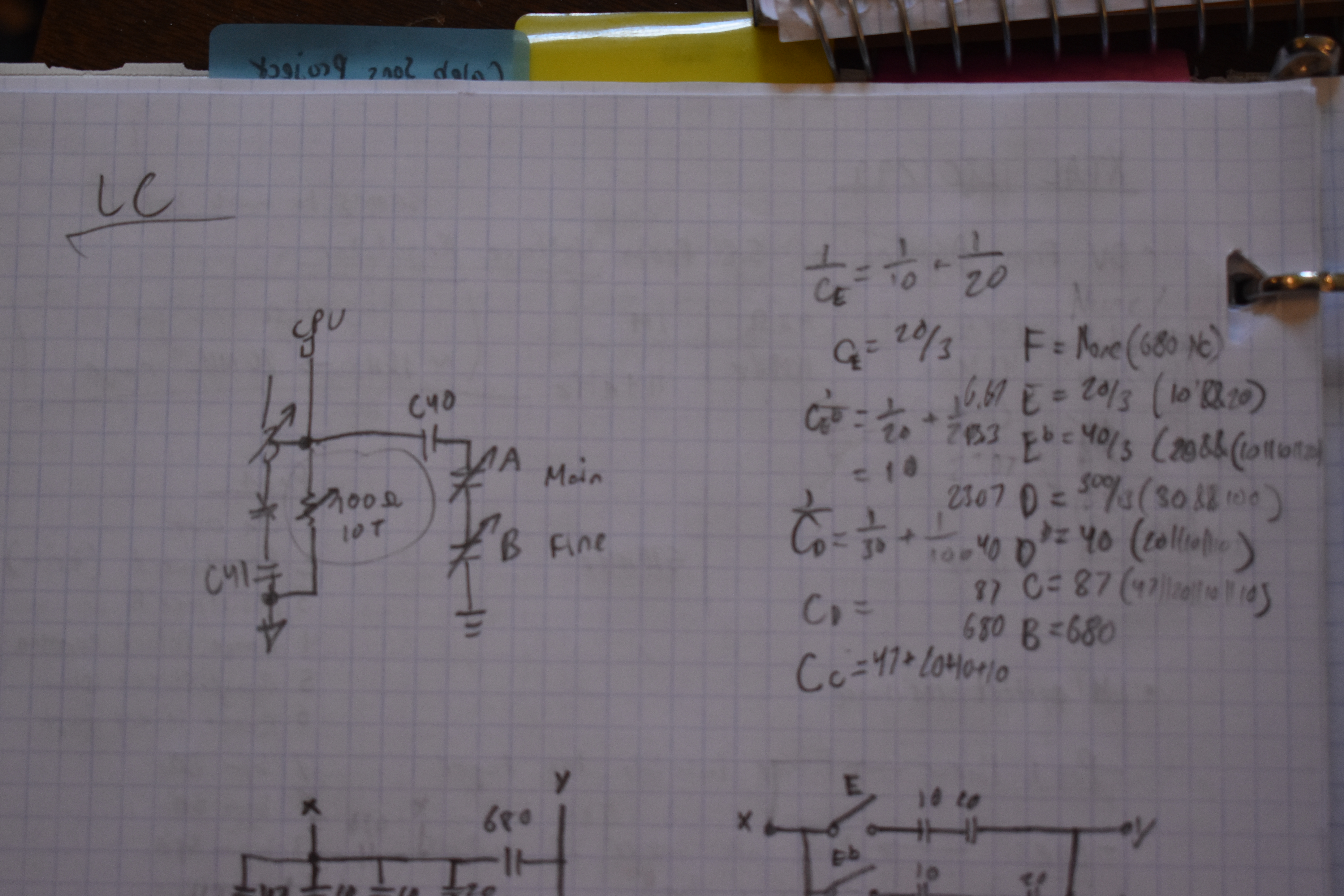
The pitch of the synth is based on the frequency of a Hartley oscillator. I've added two variable capacitors to greatly vary the pitch, one as trimmer, other as main pitch control. and just at the upper limit of before the synth begins to crash. The lower limit can still be explored. I did some experiments and found a weird way to use a 10 turn 100ohm pot (I think as a variable center-tapped inductor, since the 10 turns are coiled) to reach this super low, awesomely unstable pitch range. This really is one of the best effects, but this isn't quite as reliable as I'd like, and it does not work with the pitch varicap. I am considering using a rotary dial to choose between these two modes, but ideally, one single knob (either pot or variable cap) covering the entire pitch range.
todo:
- do math for Hartley oscillator
- stepped switches for discrete pitches
- touch node
- use motor to turn varicap for tremolo effect
There's a bunch of useful hidden functions in the software that Casio didn't build hardware for on the MT-240.

todo:
- add two glitch TONEs
- add 8 'atmosphere' buttons & control buttons (part of MT-540 ROM- maybe also add??)
- add tritone 'spam' button
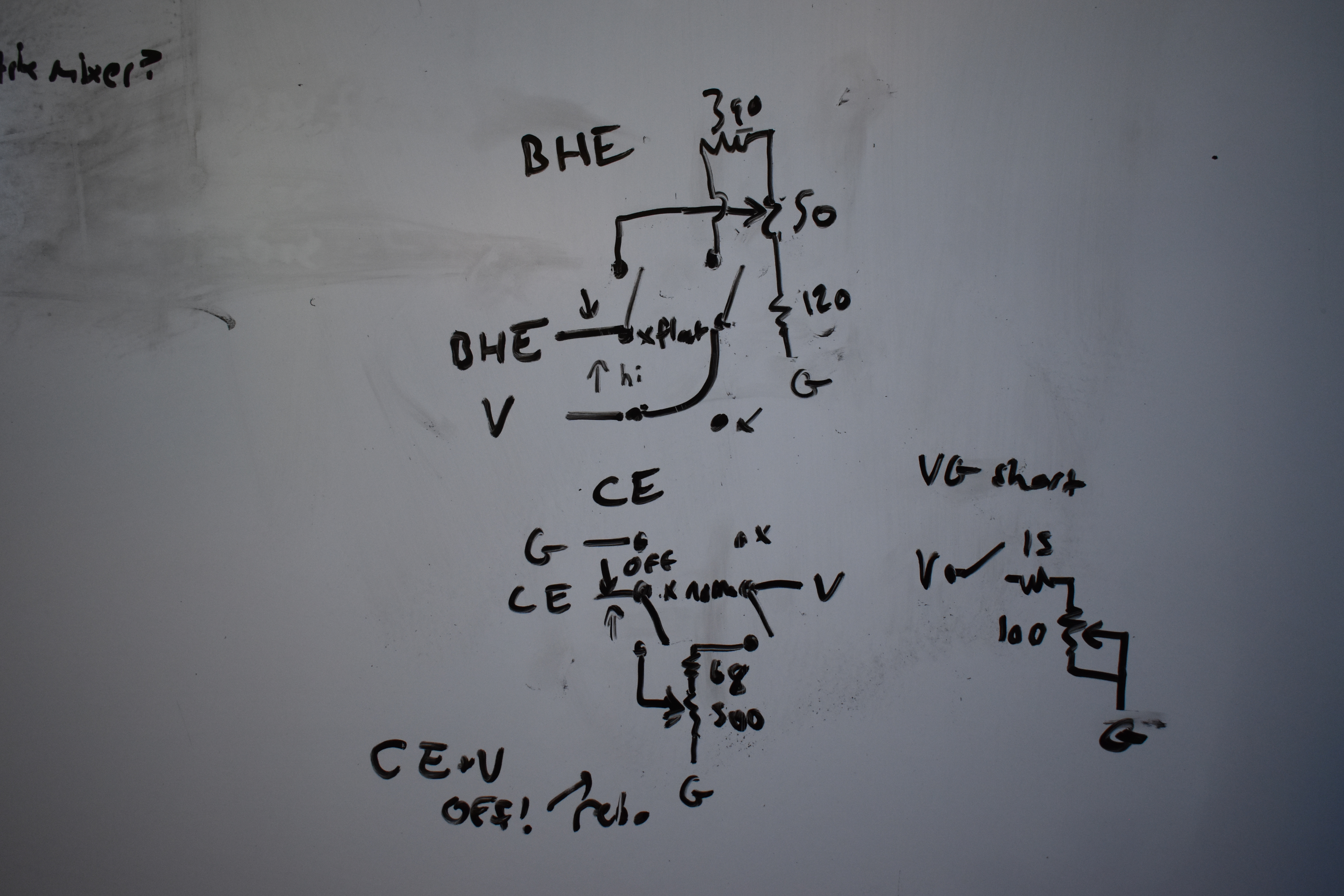
These controls affect the BHE, OE, Vss, Gnd pins on the ROM chip. The BHE and OE pins have stable digital signals that enable the ROM, but using a pot like this causes the signals to enter a disregulated mode which may glitch out or disable the ROM. Some improvements can be made so that they aren't just leaking current when not being used. The Vss & Gnd disengage switches disengage the V & G signals on the Logic Patch Bay from the ROM chip, useful for a type of quick reset with help from the uC.
todo:
- optimize BHE, OE pot circuits
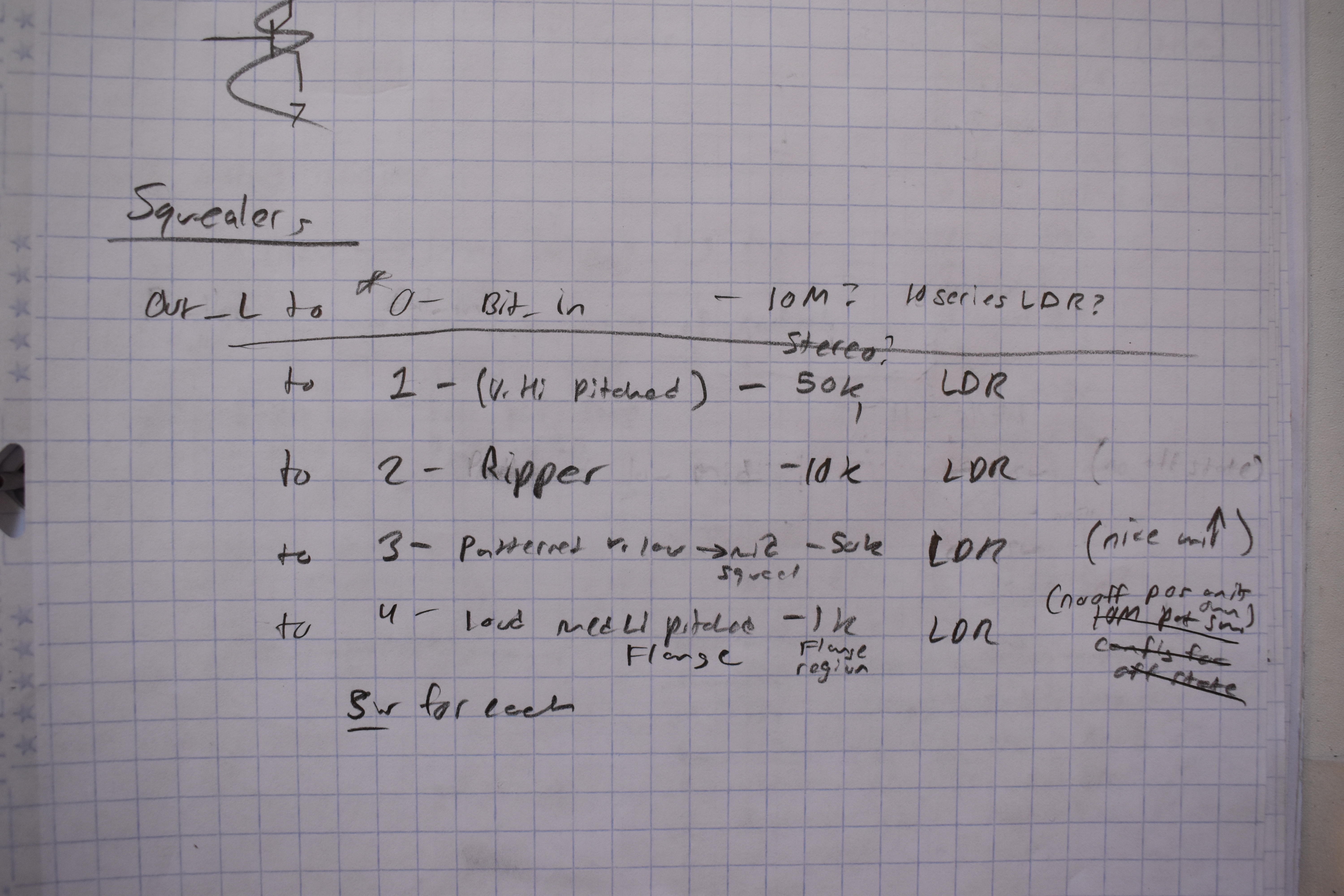
These circuits affect the DAC. I've experimented, but haven't built them yet. The Squealer scream and have all sorts of oscillating effects by creating feedback paths to the DAC inputs. These will probably affect the functionality of some or all of the other bends, when enabled, because they sort of take precedence over everything else being at the end of the audio chain. The Overdrive will probably be the most stable, and can be adjusted for intensity, it can get LOUD.They can be controlled by LDRs and uC by pulsing LEDs.